• If you currently own, previously owned or want to own an Avalanche, we welcome you to become a member today. Membership is FREE, register now!

TSB's: Driveline

sperry

Silent Avalanche RIP
SM 2007
SM 2006
SM 2005
Full Member
Joined
Oct 22, 2003
Messages
13,160
Location
Seligman, AZ
Driveline TSB's

--------------------------​

Clunk, Bump or Squawk when Vehicle Comes to Complete Stop or Accelerating from Complete Stop or Accelerating from Complete Stop (Replace Rear Drive Shaft Nickel-Plated Slip Yoke) #01-04-17-004B - (Jan 5, 2005)

1999-2000 Cadillac Escalade (Old Style)

2002-2004 Cadillac Escalade, Escalade EXT

2003-2004 Cadillac Escalade ESV

1996-1999 Chevrolet 1500 Series Extended Cab Short Box Pickup (Old Style)

1996-1999 Chevrolet 1500 Series Regular Cab Pickup and Utility Models (Old Style)

1999-2002 Chevrolet Silverado Extended Cab Short Box (New Style)

1999-2004 Chevrolet Silverado 1500 Series Regular Cab (New Style)

2000-2004 Chevrolet 1500 Series Avalanche, Suburban and Tahoe

2001-2004 Chevrolet Silverado 2500/3500 Series Regular Cab with Long Bed or Extended Cab (New Style)

2001-2004 Chevrolet Silverado 2500 Series Crew Cab, Short Box (New Style)

1996-1999 GMC 1500 Series Extended Cab Short Box Pickup (Old Style)

1996-1999 GMC 1500 Series Regular Cab Pickup and Utility Models (Old Style)

1999-2002 GMC Sierra Extended Cab Short Box (New Style)

1999-2004 GMC Sierra 1500 Series Regular Cab (New Style)

2000-2004 GMC 1500 Series Yukon, Yukon XL

2001-2004 GMC Sierra 2500/3500 Series Regular Cab with Long Bed or Extended Cab (New Style)

2001-2004 GMC Sierra 2500 Series Crew Cab, Short Box (New Style)

2003-2005 HUMMER H2

with Four Wheel Drive (4WD) or All Wheel Drive (AWD) and One-Piece Propeller Shaft ONLY

This bulletin is being revised to add Cadillac Escalade (Old Style) and HUMMER H2 to the Models section. Please discard Corporate Bulletin Number 01-04-17-004A (Section 04 -- Driveline/Axle).

Condition

Some customers may comment on a clunk, bump or squawk noise when the vehicle comes to a stop or when accelerating from a complete stop.

Cause

A slip/stick condition between the transfer case output shaft and the driveshaft slip yoke may cause this condition.

Diagnostic Tips

There are several resources in the electronic Service Information System which can provide the technician with information on diagnosis and repair of clunk conditions, and fix the customer's vehicle right the first time without unnecessary parts replacement. Some of the documents available in SI include:
  ? Symptoms - Propeller Shaft (SI Document ID #697266)
  ? Knock or Clunk Noise (SI Document ID #697290)
  ? Rear Drive Axle Noises (SI Document ID #700580)
  ? Launch Shudder/Vibration on Acceleration (Replace Propeller Shaft and Install a New Pinion Flange/Seal), Bulletin #02-04-17-001
  ? Information on 2-3 Upshift or 3-2 Downshift Clunk Noise, Bulletin #01-07-30-042
  ? Driveline Clunk When Stopping (Reprogram Powertrain Control Module (PCM), Bulletin #03-07-30-028

Correction

Replace the rear drive shaft slip yoke with a new nickel-plated slip yoke. See the parts table below.

Follow the service procedure below.

  1. Raise the vehicle on a hoist. Refer to Lifting and Jacking the Vehicle in General Information (SI Document ID #34991:cool:.
  2. Reference mark the propeller shaft to the pinion flange connection.

      Important: Do not pound on the propeller shaft yoke ears. Never pry or place any tool between a yoke and a universal joint.

  3. Remove the bolts and the yoke retainers from the pinion flange.
  4. Slide the propeller shaft forward and out of the rear pinion flange.
  5. Lower the rear of the propeller shaft and pull the driveshaft out of the transfer case.

    Notice: Never clamp propeller shaft tubing in a vise. Clamping could dent or deform the tube causing an imbalance or unsafe condition. Always clamp on one of the yokes and support the shaft horizontally. Avoid damaging the slip yoke sealing surface. Nicks may damage the bushing or cut the lip seal.

  6. Support the propeller shaft in a line horizontal with the table of a press.

      Important: Remove the front slip yoke and the universal joint together. The new nickel-plated slip yoke comes with a new universal joint.
  7. Disassemble the snap rings by pinching the ends together with a pair of pliers.
  8. If the ring does not readily snap out of the groove in the yoke, tap the end of the cup lightly in order to relieve the pressure from the ring.

normal_1222.gif


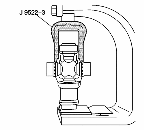
  9. Place the universal joint so that the lower ear of the yoke is supported on a 30 mm (1-1/8 in) hex head socket or a 27 mm (1-1/16 in) socket.

normal_365153.gif


  10. Place the J 9522-3 on the open horizontal bearing cups. Press the lower bearing cup out of the yoke ear.
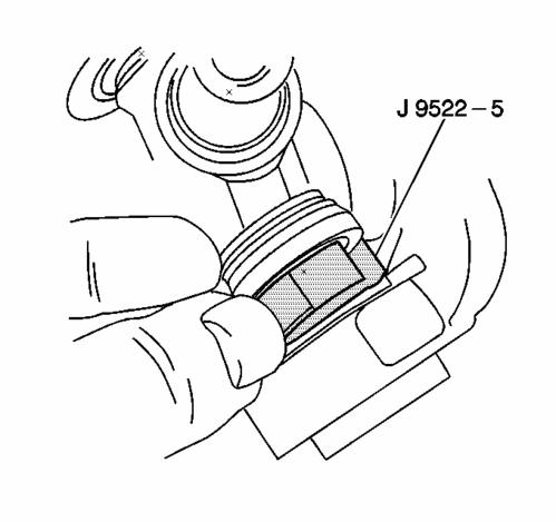
  11. If you do not completely remove the bearing cup, lift the cross and insert the J 9522-5 between the seal and the bearing cup you are removing. Continue pressing the bearing cup out of the yoke.
  12. Rotate the propeller shaft . Press the opposite bearing cup out of the drive shaft yoke.
  13. Remove the old slip yoke and universal joint.
  14. Inspect the retaining ring grooves for dirt, corrosion, or pieces of the old ring.
  15. Inspect the bearing cup bores for burrs or imperfections.
  16. Clean the retaining ring grooves. Corrosion, dirt, rust, or pieces of the old retaining ring may prevent the bearing cups from pressing into place or prevent the bearing retainers from properly seating.
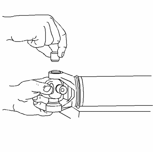
  17. Install the new nickel-plated slip yoke and universal joint. See parts table below for parts information.
  18. Remove the bearing cups from the universal joint.

normal_1223.gif


  19. Assemble one bearing cup part way into one side of the yoke. Turn the yoke ear toward the bottom.
  20. Assemble the cross into the yoke so that the trunnion seats freely into the bearing cup.

normal_1224.gif


  21. With the trunnion seated in the bearing cup, press the bearing cup into the yoke until the bearing cup is flush with the yoke ear.
  22. Install the opposite bearing cup part way into the yoke ear.
  23. Ensure that the trunnions start straight and true into both bearing cups.
  24. Press the opposite bearing cup into the yoke ear while working the cross all the time in order to inspect for free unbinding movement of the trunnions in the bearing cups.

    Important: If there seems to be a hang up or binding, stop pressing. Inspect the needle bearings for misalignment in the bearing cup.

  25. Press the bearing cup into the yoke until the bearing cup retainer groove is visible over the top of the bearing cup.
  26. Assemble the bearing retainer in the retainer groove.
  27. Continue pressing until both retainers can be snapped into place.
normal_365168.gif


  28. If the retainer is difficult to seat, the yoke can be sprung slightly with a firm blow from a soft-faced dead blow hammer.
  29. It may be necessary to lubricate the snap ring with a slight amount of chassis grease so that the snap ring seats in the bearing cup groove.
  30. Install the slip yoke onto the output shaft in the transfer case.
  31. Align the reference marks on the pinion flange and the propeller shaft.
  32. Install the yoke retainers and bolts.

      Tighten
      Tighten the yoke retainer bolts to 25 N?m (19 lb ft).
  33. Lower the vehicle.

Parts

12479383 Yoke Asm., Prop Shf Slip (without u-joint) , Nickel Plated. Must Be Ordered With U-Joint Kit P/N 12479126 - 4WD/AWD 1500 Series Suburban, Avalanche, Yukon XL, Escalade EXT, Escalade ESV with AWD (New Style)

12479126 U Joint Kit: 4WD 1500 Series Suburban, Avalanche, Yukon XL) (Escalade EXT, Escalade ESV with AWD (New Style)

Edit: Touch-up formatting.
 
Info - Driveline Clunk Noise When Shifting Between PARK and DRIVE, PARK and REVERSE or DRIVE and REVERSE #99-04-20-002C - (Jan 31, 2005)

2005 and Prior GM Light Duty Truck Models

2003-2005 HUMMER H2

This bulletin is being revised to add model years. Please discard Corporate Bulletin Number 99-04-20-002B (Section  04 -- Driveline/Axle).

Important: The condition described in this bulletin should not be confused with the following previous bulletins:
  ? Info - Discontinue Flushing and Replacing Transfer Case Fluid Due to Bump/Clunk Concern (Corporate Bulletin Number 99-04-21-004A or newer).
  ? Clunk, Bump or Squawk when Vehicle Comes to Complete Stop or Accelerating from Complete Stop or Accelerating from Complete Stop (Replace Rear Drive Shaft Nickel-Plated Slip Yoke) (Corporate Bulletin Number 01-04-17-004B or newer).


Some owners of light duty trucks equipped with automatic transmissions may comment that the vehicle exhibits a clunk noise when shifting between Park and Drive, Park and Reverse, or Drive and Reverse. Similarly, owners of vehicles equipped with automatic or manual transmissions may comment that the vehicle exhibits a clunk noise while driving when the accelerator is quickly depressed and then released.

Whenever there are two or more gears interacting with one another, there must be a certain amount of clearance between those gears in order for the gears to operate properly. This clearance or freeplay (also known as lash) can translate into a clunk noise whenever the gear is loaded and unloaded quickly, or whenever the direction of rotation is reversed. The more gears you have in a system, the more freeplay the total system will have.

The clunk noise that owners sometimes hear may be the result of a buildup of freeplay (lash) between the components in the driveline.

For example, the potential for a driveline clunk would be greater in a 4-wheel drive or all-wheel drive vehicle than a 2-wheel drive vehicle. This is because in addition to the freeplay from the rear axle gears, the universal joints, and the transmission (common to both vehicles), the 4-wheel drive transfer case gears (and their associated clearances) add additional freeplay to the driveline.

In service, dealers are discouraged from attempting to repair driveline clunk conditions for the following reasons:
  ? Comments of driveline clunk are almost never the result of one individual component with excessive lash, but rather the result of the added affect of freeplay (or lash) present in all of the driveline components. Because all of the components in the driveline have a certain amount of lash by design, changing driveline components may not result in a satisfactory lash reduction.
  ? While some owners may find the clunk noise objectionable, this will not adversely affect durability or performance.
  ? For additional diagnostic information, refer to the appropriate Service Information.
 
Info - Driveline Characteristics for All-Wheel Drive (AWD) and Four-Wheel Drive (4WD) Systems #01-04-18-001C - (Nov 18, 2004)​

2005 and Prior Cars and Light Duty Trucks with Four-Wheel Drive (4WD) or All-Wheel Drive (AWD)

2003-2005 HUMMER H2

This bulletin is being revised to add additional model years. Please discard Corporate Bulletin Number 01-04-18-001B (Section 04 -- Driveline/Axle).

The purpose of this bulletin is to help explain the operating characteristics of 4WD/AWD systems.

For specific operating instructions for individual transfer cases, please refer to the Owner's Manual or Service Information.

DEFINITIONS

AWD vs. 4WD

The very basic difference between AWD and 4WD is the intended usage of the systems.

AWD is usually intended for on-road use in inclement weather conditions, while operating smoothly on dry pavement by allowing for a difference in speed between the front and rear axles while turning. These systems are not selectable and do not have low range gearing for the transfer case. These systems can be found in cars or trucks.

4WD is primarily found in trucks and can be broken down into Part-Time, Full-Time, and Automatic Transfer Cases. These selectable systems have modes intended for on-road use and other modes intended for off-road or low traction situation usage. All current GM 4WD systems have a low range available in the transfer case.

CHARACTERISTICS

Disclaimer: Even though a certain amount of noise or feel can be expected, GM may offer service procedures or components, or change vehicle design, which may reduce perceived noise levels in the interest of customer satisfaction.

AWD

There are two different categories of AWD systems. The first category is full-time AWD. This type of transfer case delivers torque to the front and rear axles at all times. This ratio can vary depending on the system, but is usually about a 30/70% front to rear split but also can vary depending on traction conditions, up to 100% front or rear. This type of transfer case can have a viscous coupling for low traction conditions along with a planetary gear set to allow for difference in speeds between the front and rear axle, or an open type of planetary gear set differential, which uses brake based traction control for low traction conditions. An example of a vehicle with an open differential/traction control type of transfer case is a 2003 Escalade. RPO codes for these types of transfer cases are NP3 (NVG 149, BW 4473) or NR3 (BW 4476, 4481).

The second category is an on-demand AWD. This type of AWD basically delivers torque only to a primary driving axle unless reduced traction is experienced. At that point, the system electronically or mechanically will apply torque to the other axle. Depending on the type of system, this can provide up to 100% of the torque to the axle with traction. These transfer cases use an electronically actuated clutch pack, a hydraulically actuated clutch pack, or a viscous coupling to allow for a difference in speed between the front and rear axles. An example of an electronically controlled version of the On-Demand AWD is in the Smart Trak system in the 2003 Bravada. An example of a hydraulically operated On-Demand AWD is the Versa Trak system in the Aztek, while a viscous coupling is used in the Vibe. The RPO code for the Bravada is NP4 (NVG126). For some vehicle lines, there is not an RPO code. The only way to tell is by the Line Chassis VIN code, B for the Rendezvous/Aztek, V for the Venture/Montana or by SM for the Vibe.

PART-TIME 4WD

Part time 4WD refers to vehicles equipped with a transfer case to split power between the front and rear axles of the vehicle. This traditionally is a 2-speed selectable transfer case that can be shifted into 2HI, 4HI, 4LO and usually a Neutral position. The 4WD modes of Part time systems do not allow for a difference in speed between the front and rear axles while turning. This system effectively locks the front and rear propeller shafts together. When turning, the tires must allow for the different turning radius of the front and rear axles, which is why this is intended for low traction or off-road use. These systems have low range gearing for the transfer case. An example of a vehicle with this style of transfer case would be a Silverado with a manual shift transfer case (a shift lever on the floor) (RPO NP2) or a Colorado with a push button transfer case with a 2HI, 4HI, 4LO and Neutral position (RPO NP1). The RPO codes for this style of transfer case are NP1 (NVG 233, 243, 263, and T-150) or NP2 (NVG 231, 241,261, BW 4401, 4470).

FULL-TIME 4WD

A second version of a 4WD transfer case is a full-time 4WD transfer case. This style of transfer case has an open center differential to allow for different speeds between the front and rear axles and operates similar to an AWD system. This transfer case can be locked to operate like a Part-Time 4WD transfer case (no difference between front and rear prop-shaft speeds) and/or uses a traction control system to assist in low traction situations. These transfer cases also have a selectable low range. An example of this type of 4WD is the H2. RPO code is NR4.

AUTOMATIC TRANSFER CASES

The last category is a combination of 4WD and On Demand AWD. These transfer cases have a 2HI, Auto-4WD, 4HI, 4LO and Neutral position and would fall in the general 4WD category. This transfer case has the operating characteristics of both an On Demand AWD and a Part-Time 4WD system depending on the mode selected. This transfer case uses a clutch pack to allow for a difference in speed between the front and rear axles in the Auto-4WD mode. In the 4HI or 4LO modes, there is no allowance for the difference in speed between the front and rear axles. An example of a vehicle with this would be a Sierra with a push-button transfer case with a 2HI, Auto-4WD, 4HI, 4LO, and Neutral positions. The RPO code for these transfer cases is NP8 (NVG 226, 236, 246, 246 EAU).

DIAGNOSTIC AIDS

Always follow Strategy Based diagnostics and service information in the Electronic Service Information (eSI). eSI is constantly updated with new and more thorough information.

One of the first steps that can be used in determining if a noise is a characteristic is to compare it to a similar vehicle. The comparison vehicle should be as close to the original vehicle as possible, including mileage, GVW, RPO, chassis style (extended cab, short-bed...).

Attempts to correct characteristic types of noise and/or feel should not be performed. In most situations, these conditions will not be changed. Any attempts to correct these conditions may reduce customer confidence and inconvenience the customer while their vehicle is out of service.

4WD

While operating 4WD vehicles in the 2HI mode, they should perform similarly to an equivalent 2WD version of the vehicle. However there are still additional components on the vehicles and there may still be some slight differences in characteristics. Some Part-Time 4WD transfer cases may make a slight gear rattle type of noise when operated in 2HI at low engine speeds, similar to a manual transmission gear rattle type of noise. This can originate in the synchronizer assembly from engine harmonics. This noise will usually be reduced or eliminated while driving in a 4WD mode because the synchronizer assembly clearances will be taken up once engaged in 4WD. Operating the engine at a slightly higher rpm should reduce this noise.

While a vehicle is traveling down the road, the tires rotate a certain number of times per mile depending on the true tire radius. If all the tires do not have the exact same true radius (due to load, tire pressure, wear, build variances...), they will turn at slightly different rates. Also, unless the vehicle is traveling in a perfectly straight line, the front and rear axles are traveling in a slightly different arc, which means the front and rear axles are traveling at slightly different average speeds.

These systems either do not have a center differential or it has been bypassed (when used in 4HI or 4LO in Part-Time or Automatic systems, or 4HI Lock or 4LO Lock on Full-time 4WD), so the front and the rear propeller shafts will turn at the same speed, which leads to the front, and rear axles rotating at the same average speed. Using the 4WD modes (4HI, 4LO, 4HI Lock, 4LO Lock) will usually increase noise in the axles, transfer case and the rest of the driveline and is usually greater at higher speeds and will usually increase the more the vehicle is turned. As the vehicle turns, the front and rear axles follow a different arc. When this occurs, the only place to compensate for this binding is between the contact patch of the tires and the ground. This can feel like the vehicle is vibrating, crow hopping or grabbing. Even if the vehicle is driven in a straight line, there are slight differences in tire circumference that will cause some driveline binding. If a vehicle had the exact same size tires and was driven in a perfectly straight line, the fact that more parts are moving would mean that there would be more noise and possibly some feel of the system operating.

Use of 4HI or 4LO and 4HI Lock or 4LO Lock on Full-time 4WD is intended for use on a low traction surface such as snow, ice, mud or sand. On a low traction surface, the differences in front and rear axle speeds will not have as much effect on binding because of the lower traction levels between the surface and the contact patch of the tires. On a high traction surface, the higher traction levels will create more binding in the driveline.

As a result, a small amount of noise or feel of the system operating can be expected when using 4HI or 4LO in Part-Time or Automatic systems, or 4HI Lock or 4LO Lock on Full-time 4WD. The noise and feel can vary depending on the transfer case type, GVW ratings (generally the higher the GVW the more noise it will make), vehicle build variations, gear ratios in the axles, axle type, tires, and importantly driving conditions.

While the transfer case is in Neutral, with the engine running, some noise can be expected.

When transfer case is shifted to 4LO (or any time through or from neutral, for example from 2HI to 4LO or back) with the engine running, or with the vehicle moving, some grinding noise can be expected. In some vehicles you may experience a slight bump as the shift to 4LO is completed. This occurs because the 4LO range is not synchronized and there may be a difference in transfer case input shaft and output shaft speeds, especially if the vehicle is moving or equipped with an automatic transmission (residual torque from the transmission may be driving the transfer case input shaft). To minimize this noise the shift may be completed at a stop and in an engine off, key on mode. However, there may be an increased chance of having a blocked shift (some models must have the engine restarted to complete the shift). Noise and bump levels will vary between vehicles and even between shifts on the same vehicle. As a reminder, if attempting to determine if noise or bump experienced in one vehicle is a characteristic, be sure to compare to similar make vehicles. For example the shift to 4LO in a Colorado or Canyon will usually have more noise and/or bump feel than in a Silverado or Sierra. When driving in 4LO, the extra gear reduction will make additional noise compared to driving in 4HI. The automatic transmission shift characteristics will also feel different while operating in 4LO

AWD

AWD systems are intended for use in high and low traction situations without operator input. These systems will generally be quieter on high traction surfaces than a similar 4WD used in 4HI or 4LO. However, these systems will generally make more noise than a similar 2WD vehicle simply because there are more parts rotating and more gear sets interfacing. Once again, these systems may make more noise in turns, and in some situations you may be able to feel the system operating, even on high traction surfaces. Additionally, you may feel transfer case operation in on-demand AWD systems. These systems generally react to a speed difference between the front and rear axle and it may be possible to detect this by hearing a noise, or actually feeling the engagement of the system.

Automatic Transfer Cases

Automatic transfer cases will have the characteristics of both the Part-Time 4WD and the AWD systems depending on the mode selected. If the transfer case is operated in 4HI or 4LO, it will behave as a Part-Time 4WD system. If it is operated in the Auto 4WD mode, it will behave like an on-demand AWD system.

Driveline noises in 4WD or AWD vehicles caused by loading may be mistaken for transfer case or front axle noise because they can sound very similar. Four-wheel drive noises caused by loading may exhibit the following conditions:
  ? The noise will be greatest on a clear, dry road and decrease on a low traction surface. Front axle or transfer case noise caused by bearings, ring and pinion, or planetary gearing will be same similar on all surfaces.
  ? The noises or feel that can be expected will increase while making a tight turn.
  ? The noises may be changed from a deceleration to an acceleration condition (or acceleration to deceleration) by raising or lowering tire pressure at one end of the vehicle.

TIRES

Tire rolling rates can be a major factor in operational characteristics. Consider the following important items:
  ? All tires are the same size and brand. Tires of different brands may have different circumferences (or radius) even if they are the same size.
  ? Tires are set to factory recommended pressures. A tire with low air pressure will roll at a different rate.
  ? All tires have approximately equal amounts of wear. Tires with different amounts of wear will roll at different rates.
  ? All tires are the same tread type. Don't mix on-off road, all-season or street tires on the same truck as they may have different circumferences and roll at different rates.
  ? One or more of the tires may show small, short scratches around the circumference of the tire tread. The tire "scuffing" on the road surface causes these scratches.
 
Whine Noise from Rear Axle (Diagnose and Replace Rear Shaft with Tuned Torsional Tamper Rear Propeller Shaft) #03-04-17-001C - (Apr 8, 2005)

2002-2005 Cadillac Escalade EXT

2003-2005 Cadillac Escalade ESV

2000-2005 Chevrolet Suburban 1500 Series

2002-2005 Chevrolet Avalanche 1500 Series

2000-2005 GMC Yukon XL 1500 Series, Yukon XL Denali

This bulletin is being revised to add the 2005 model year and the Cadillac ESV model. Please discard Corporate Bulletin Number 03-04-17-001B (Section 04 - Driveline/Axle).

Condition

Some customers may comment on a slight axle whine heard only at certain speeds, typically between 72-96 km/h (45-60  mph).

Cause

"Inherent" ring and pinion gear whine.

All gear driven units, such as automotive rear axles, produce some level of noise that cannot be eliminated with conventional adjustments and repairs. "Inherent" axle noise can be described as a slight noise heard only at a certain speed (typically between 72-96 km/h (45-60 mph) on most General Motors? trucks). The presence of this noise is not indicative of a functional concern with the axle assembly. However, some customers may find that this "inherent" axle noise is unacceptable.

Correction

Replace the rear propeller shaft with a tuned torsional damper shaft ONLY after diagnosis concludes that it is an "inherent" rear axle noise and no physical damage or incorrect adjustment exists.

      Important: If the noise is not correctly diagnosed as "inherent" and having a peak in the narrow speed range of 72-96 km/h (45-60 mph), the addition of a tuned torsional damper propeller shaft can aggravate the perceptible noise level. It is extremely important to first diagnose the rear axle noise as "inherent" before installing a new tuned torsional damper propeller shaft.

Diagnostic Information and Procedure for Rear Axle Noise

  ? Diagnostic Starting Point - Rear Drive Axle (SI Document ID #696972)
  ? Symptoms - Rear Drive Axle (SI Document ID #697220)
  ? Rear Drive Axle Noises (SI Document ID #700580)
  ? Noisy in Drive (SI Document ID #698120)

    Rear Propeller Shaft Replacement

  1. Safely raise the vehicle.
  2. Remove the bolts and the yoke retainers from the rear axle pinion yoke.

      Notice: When removing the propeller shaft, do not attempt to remove the shaft by pounding on the yoke ears or using a tool between the yoke and the universal joint. If the propeller shaft is removed by using such means, the injection joints may fracture and lead to premature failure of the joint.

  3. Slide the propeller shaft forward in order to disconnect the propeller shaft from the rear axle pinion yoke.
  4. Slide the propeller shaft rearward in order to disconnect the propeller shaft from the transmission or transfer case.
  5. Remove the propeller shaft from the vehicle and discard.
  6. Install the new tuned torsional damper propeller shaft (see Parts Information below) into the transmission or transfer case.
  7. Install the propeller shaft to the rear axle pinion yoke.
  8. Install the yoke retainers and bolts.

      Tighten
      Tighten the yoke retainer bolts to 25 N?m (19 lb ft).

  9. Lower the vehicle.
  10. Road test the vehicle.
 
Back
Top