No Start, No Crank, Battery, Batteries, Generator, Gages, SES, SIR, Brake, Security, Theft, ABS, Hot, DIC Messages, Lamp, Light, Battery and Generator Diagnostic Testing and Cadillac Roadside Service, #02-06-03-006B - (Nov 10, 2004)
1997-2005 Passenger Cars and Trucks (Except Electric Vehicles)
2003-2005 HUMMER H2
This bulletin is being revised to add the 2004 and 2005 model years. Please discard Corporate Bulletin Number 02-06-03-006A (Section 06 - Engine).
IF YOU WISH TO PRINT THE ELECTRICAL SYSTEM DIAGNOSTIC WORK SHEET ONLY, YOU MAY REFER TO CORPORATE BULLETIN NUMBER 02-06-03-011.
Note: Some Dealer/GM specific content removed, This document posting is for reference only, NOT for the professional use of which it is intended.
Condition
Some customers may have comments regarding any one or more of the following conditions:
1. Intermittent illumination of one or more of the following instrument panel warning lamps:
- SES light
- Generator light
- SIR light
- Brake light
- Security, theft light
- ABS light
- Hot light
2. Gage readings which seem to be incorrect.
3. Erratic RPM display on the Tachometer.
4. Engine is difficult /hard to start.
5. Engine will not crank.
6. Check Generator displayed on the Driver Information Center.
7. The transmission shifts hard.
8. Noise underhood: growl, rattle, hiss/tapping, grinding.
Quality improvement is a goal of General Motors. As part of the ongoing quality improvement assessment efforts for generators and batteries, General Motors is implementing a new product feedback process.
Generator/Battery Service/Feedback Process
Accurate feedback from technicians will allow General Motors to accurately inspect and diagnose batteries and/or generators replaced in the field.
Why? Testing of the batteries and the generators replaced and returned to General Motors have shown that an extremely high percentage of them are operating within design specifications, also known as Trouble Not Found (TNF).
Therefore, General Motors is modifying the battery and generator testing procedure and supporting documents required when a battery or generator is replaced under warranty.
Testing Procedures
Caution: Batteries produce explosive gases, contain corrosive acid and supply levels of electrical current high enough to cause burns. Therefore, to reduce the risk of personal injury when working near a battery, always shield your eyes and avoid leaning over the battery whenever possible. Do not expose the battery to open flames or sparks. Do not allow the battery electrolyte to contact the eyes or the skin. Flush immediately and thoroughly, any contacted areas with water and get medical help.
Proper Testing requires that the following test procedures be followed.
Important: Complete the "Electrical System Diagnostic Work Sheet" as you perform the test steps outlined below. IF YOU WISH TO PRINT THE ELECTRICAL SYSTEM DIAGNOSTIC WORK SHEET ONLY, YOU MAY REFER TO CORPORATE BULLETIN NUMBER 02-06-03-011.
Battery Inspection and Test Portion.
1. Inspect the battery for evidence of physical damage or leakage. If damage or leakage is found, replace the battery. If no damage or leakage is found, proceed to Step 2.
Leaking batteries are to be claimed using failure code "6J" and do not require a Midtronics test code.
- If the battery has leaked, the battery tray and surrounding area should be neutralized with a baking soda and water solution. (This is a Straight time: Add operation requiring Service Management authorization).
- If the battery has leaked and soaked the battery insulator blanket, a new battery insulator blanket must be installed on the new battery.
2. Is the hydrometer eye, if equipped, clear (low electrolyte level)? If clear, tap the hydrometer lightly with the handle of a small screwdriver. Did the color change? If no, replace the battery. If yes, continue with Step 3.
Important: The pad/post of the battery must make solid and complete contact with the terminal/connector pad of the battery cable. This interface must be clean and corrosion free. The positive terminal is always sealed to the case by the vinyl covering on the battery cable end. On many vehicles, the negative terminal is also sealed. The attachment bolt is to hold the battery cable end terminal firmly on the battery. It is not designed as the carrier of the current.
3. Attempt to rotate both battery cables. Properly torqued battery cables will have a break-away torque requirement of 15 N?m (10 lb ft). If the bolt is tight and the battery cable end does not rotate, continue with the next step. If the bolt is tight and the battery cable end rotates, it may be due to one of the following conditions:
- The battery cable end may be damaged. Inspect and replace the damaged component as required.
- The attaching bolt is cross threaded. Refer to Corporate Bulletin 02-06-04-015 for the proper repair procedure.
- The attaching bolt may be too long. Replace the battery cable bolt, if necessary.
- Inspect for the presence of foreign material lodged in the battery bolt hole. Repair as necessary.
4. Connect the Midtronics Digital Battery Analyzer, (tester), J 42000 to the battery terminals. Rock the J 42000 Battery Tester clips back and forth on the cable attaching bolts to cut through any coating or oxidation that may be present. For further information regarding the tester refer to: Testing the Battery with the Midtronics Micro 410 Tester, J 42000, found later in this bulletin.
Important:
? For AGM batteries, you must enter 100 CCA more than the CCA value displayed on the battery label, when using the Midtronics Digital Battery Analyzer, J 42000.
? THE "CCA" READING DISPLAYED ON THE J 42000 SHOULD "NOT" BE COMPARED WITH THE BATTERY'S LABORATORY CCA RATING SHOWN ON THE BATTERY LABEL. THESE NUMBERS ARE NOT RELATED AND ARE ARRIVED AT IN COMPLETELY DIFFERENT WAYS. THE "CCA" NUMBER SHOWN ON THE TESTER WILL JUST ABOUT ALWAYS BE LOWER THAN THE OFFICIAL CCA RATING OF THE BATTERY AND SHOULD NOT BE A CONCERN.
5. Enter the correct CCA of the battery in the vehicle into the Midtronics Tester, J 42000.
6. Test the battery with the Midtronics Digital Battery Analyzer, J 42000. The tester will display one of five messages. Refer to the appropriate message below for the next step.
- Good battery. (Proceed to the Generator Testing portion of the work sheet).
- Good-Recharge. (Recharge the battery. Refer to Corporate Bulletin Number 02-06-03-009A Return to Step 4).
- Charge & retest. In this case, the tester has determined the battery state of charge is too low to perform an adequate test. (Recharge the battery. Refer to Corporate Bulletin Number 02-06-03-009A. Return to Step 4).
- Replace battery. Return to Step 4.
- Bad cell - Replace. Go to Step 7.
7. THE "CCA" READING DISPLAYED ON THE J 42000 SHOULD "NOT" BE COMPARED WITH THE BATTERY'S LABORATORY CCA RATINGSHOWN ON THE BATTERY LABEL. THESE NUMBERS ARE NOT RELATED AND ARE ARRIVED AT IN COMPLETELY DIFFERENT WAYS. THE "CCA" NUMBER SHOWN ON THE TESTER WILL JUST ABOUT ALWAYS BE LOWER THAN THE OFFICIAL CCA RATING OF THE BATTERY AND SHOULD NOT BE A CONCERN.
If a "Replace Battery" or "Bad cell - Replace" message is displayed on the J 42000, the following steps must be performed before replacing the battery.
- Disconnect both battery cables.
- Clean the battery terminal pads.
- Install test adapters.
Important: Failure to provide the Midtronics "Out of Vehicle" seven digit test code on the warranty claim may subject the claim to rejection.
Perform the Midtronics out of vehicle test.
- Record the 7 digit code on the repair order and the work sheet.
- Replace the battery. Return to Step 4 and test the replacement battery.
Important: THE "CCA" READING DISPLAYED ON THE J 42000 SHOULD "NOT" BE COMPARED WITH THE BATTERY'S LABORATORY CCA RATING SHOWN ON THE BATTERY LABEL. THESE NUMBERS ARE NOT RELATED AND ARE ARRIVED AT IN COMPLETELY DIFFERENT WAYS. THE "CCA" NUMBER SHOWN ON THE TESTER WILL JUST ABOUT ALWAYS BE LOWER THAN THE OFFICIAL CCA RATING OF THE BATTERY AND SHOULD NOT BE A CONCERN.
8. Test the replacement battery with the Midtronics tester J 42000, start with Step 4.
Charging System Test
Important: Battery voltage must be higher than 12.4 volts for proper electrical system testing. Without an adequately charged battery, testing of a vehicle generator will result in the replacement of good generators. Therefore, the following test procedures should be followed:
1. Key in the "OFF/LOCK" position, with a digital multimeter, measure and record the battery voltage at the battery terminals,______Volts. This is known as battery voltage.
2. Turn "OFF" all accessories.
3. With the engine running, with a digital multimeter, measure and record the battery voltage at the battery terminals,______Volts. This is known as system voltage.
4. Is the system voltage reading greater than the battery voltage, but less than 16 volts? Is it? If yes, go to Step 7. If no, go to Step 5.
5. If no, with the engine running, measure the voltage output of the generator at the generator.___volts.
6. Was Step #5 voltage greater than the voltage obtained at the battery, Step #3. If yes, a wiring related condition exists with the vehicle. The generator output is not reaching the battery. Diagnose and repair.
7. With the key "ON", engine "OFF", what is the ignition 1 voltage displayed on the Tech 2??____volts
8. Start the engine. What is the ignition 1 voltage displayed on the Tech 2??_____volts
9. Engine running voltage should be greater than engine "off" voltage, but less than 16 volts. Is it?
10. What is displayed on the Tech 2? for Terminal "L" ? (If available).________________
11. What is displayed on the Tech 2? for Terminal "F" ? (If available).________________
12. Refer to Service Information (SI), Generator Usage Table, forthe vehicle being tested and determine the Load Test and Rated Output values of the generator for the vehicle being tested.
13. Connect the Sun Vat 40 Tester, or equivalent, to the vehicle. Remember the aqua/blue clamp needs to be placed on the generator output cable(s) as close to the generator as possible. Connect the red clamp to a positive terminal and the black clamp to the engine or a vehicle ground connection.All connections should be made as close to the generator as possible.
14. With the engine idling, what is the idle RPM _________and the generator ampere output?________amps
15. Increase the engine speed to 2000 RPM (cars) 2500 (trucks),(highway speed). Use the Sun Vat 40 to place a load on the generator. Adjust the load to the Load Test output value given in the Service Information (SI) for the vehicle (or use 70% of the rated output). Record the generator output__________amps and the ignition 1 or system voltage________ volts.
16. Is the ignition 1 or system voltage 13-16 volts? (circle one) yes no If not, (or if the Load Test output value could not be reached), replace the generator.
Important: Battery testing procedures should be followed after returning to the dealership.
The technician should take the battery back to the dealership and perform a Midtronics test, J 42000.
? The code should be included in the comment section of the warranty claim when the claim is submitted.
? If the battery is found to test good, note the code in the comment section of the claim followed by the verbiage BATTERY GOOD - ROADSIDE REPAIR.
Background Information
Batteries
What is a battery? The battery is a reservoir. Think of a battery asa water tower (reservoir) for your city's water system.
The water tower stands some 60 feet in the air. The forces of gravity on the volume of water in the tower determines the pressure within the system.
Opening a valve in the water system allows water to flow through the pipes to the consumer. Water flowing from the tower lowers the force of gravity (pressure) on the volume of water standing in the tower. If the water is not replaced, pumped into the water tower (recharged), the water system pressure would drop. The volume of the water being released from the system determines the discharge rate.
When defining pressure in an electrical circuit, the term volts is used as compared to pounds per square inch in other systems.
A battery is made up of 6 individual cells. Each individual cell is able to store a small amount of pressure (voltage). Each individual cell has the capacity of approximately 2.1 volts (pressure). When the 6 individual cells are connected in series, you have a 12.6 volt battery. The pressure (voltage) of the battery may be measured and displayed on a digital multimeter.
A piece of stranded wire, with only one strand (which could be as small as the hair on your head) making contact with the battery source, will show either battery voltage with the engine off, or system voltage when the engine is running.
Voltage readings do not indicate the volume of (current/amperage) electrical energy available. Your diagnostic routine must determine the amount of electrical energy (amperage) available.
For example, a new AAA battery, as used in a flash light, has a voltage level of approximately 1.6 volts. If you place 8 AAA flash light batteriesin series and measure them with a multimeter, the result will be a readingon the multimeter exceeding 12 volts. The question: will this 12 volts start a vehicle engine? The answer is No. Why not? The volume (amps) is not sufficient to energize the cranking motor.
Amperage/current are terms used to define the volume of electrical energy within an electrical circuit. Batteries store amperage under pressure (voltage).
Turning on a switch within an automotive electrical system allows current (amperage) to flow through the connecting wires to the consumer (the consumer in an electrical system is any motor, bulb, actuator or other device). The current (amperage) flowing from the battery reduces the voltage (pressure).If the current/amperage is not replaced by charging, battery voltage will drop.
Think of it this way. Amperage does the work; voltage is the pressure.When you touch a 110 volt AC current source at home, you get quite a shock because of the amperage available. How many of you have seen another technician or yourself feel the wallop of the ignition systems 40,000 + volts. There is very little current here, however, if the amperage were higher, the technicianwould suffer extreme consequences.
What does a battery green eye really mean? A green eye means the cell in which the eye is placed is more than 65% charged, however, other cells in the battery may be low on electrolyte, or a cell may be internally shorted and the battery may not perform properly. The green eye is an indicator of the state of charge of that particular cell. The green eye is an attempt, when all things in all cells are equal, to give a hydrometer indication of the one cell and apply that to the entire battery. To properly test a suspect battery, you must use the Midtronics Battery tester.
Testing the Battery with the Midtronics Micro 410 Tester, J 42000
Important: The Midtronics Micro 410, J 42000, (tester) helps identify battery problems. However, it is NOT CAPABLE OF TESTING THE CHARGING SYSTEM (GENERATOR) OR PERFORMING PARASITIC LOAD TESTS.
The Midtronics Digital Battery Analyzer, (tester), J 42000, should be used to determine the state of health and charge level of the battery prior to any battery or generator replacement (unless physical damage is found to either the battery or the generator). The tester, J 42000, uses conductance technology instead of traditional load testing. The tester allows you to test most batteries that are partially discharged without first performing the time consuming charging and load testing procedure. The tester helps quickly identify batteries that are serviceable and just need to be re-charged. Battery testing is best performed in the vehicle at the battery terminals. If you cannot access the battery terminals, remove the battery and test the battery out of the vehicle. As with any electrical test, a good connection is very important to battery testing.
Generators
The automotive generator is a highly complex electromechanical device.Generators apply the principles of magnetic induction to automotive electrical systems to supply proper current (amperage) and voltage (pressure) regulation during all driving conditions.
Proper testing of the generator requires that the battery be at a full state of charge. The generator's voltage and ampere outputs will be controlled/regulated based on the battery's state of charge. The generator's internal voltage regulator monitors the vehicle system voltage and will control the charging system voltage output. Controlling the charging system in the range of 13.5 to 16.0 volts prevents over/under charging of the battery, depending on the generator used in the vehicle.
Generators internally produce alternating (AC) current. Before it reaches the generator's output terminal, conversion to direct (DC) current is required for automotive use.
All generators use a voltage regulator to regulate the amount of voltage (pressure) the generator maintains on the system.
All generators have a specified or designed maximum amperage (volume) rated output capacity.
A series of 6 diodes, in a rectifier system, (rectifier bridge), converts AC to DC voltage and current.
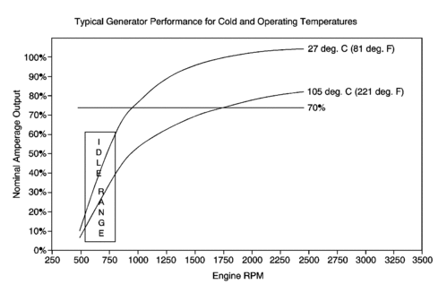
The faster a generator's rotor spins, the higher the available output of current (amperes). Generator output is directly related to engine speed (high engine speed = high available current output; low engine speed (idle) = low available current output).
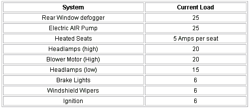
Ampere output of the generator must be larger than the vehicle usage requirements or a battery discharge condition will occur.
A generator operating at engine base idle may not charge a battery unless all consumers of energy, i.e., A/C, heated seats, rear window defogger, headlights, etc. are off, and then only a small current (ampere) level may be charging the battery.
For example, a generator with a rated output of 100 amps, at 1500 engine RPM, will show the following characteristics when a diode within the rectifier bridge has a problem:
? The generator with one failed positive diode will produce the proper regulated voltage however, only about 66 amps output.
? If two positive diodes are defective, the generator will still produce the proper regulated voltage. However, only about 1/3 (33 amps) of rated output will be available.
? Failed negative diodes have an effect, too, but this is generally related to shortened generator life and not to reduced output.
Consider a hypothetical example. If a vehicle requires 65 amps of current to maintain vehicle operation (i.e. radio, heater, heated seats, air conditioning, clock, memory modules, and the list goes on), at idle (650 RPM),the generator produces, say 50 amps. The balance is made up by the battery. If the generator produces 100 amps at 2000 RPM, 65 amps are used by the vehicle and the excess (35 amps), is available for recharging the battery. Over time, the generator replenishes the battery and keeps it in a fully charged state.
A customer who only drives the city streets at low speeds, especially in the winter with the headlights, heated seats, wipers, rear window defroster, and heater blower on, is discharging the battery. For a generator to produce maximum output, the engine speed must be in the 2000 RPM range or higher.
Batteries are like people in some ways. They work best when the ambient temperature is around 22?C (72?F). At a temperature of -17?C (0?F), the battery is only 60 % efficient. At high ambient temperatures above 27?C (80?F), the battery wears out quicker due to the catalyst effect of temperature on the chemicals within the battery.
Battery Charging
Before charging a battery, inspect the battery for the following:
? Inspect the battery for evidence of physical damage. If damage is found, replace the battery. If no damage is found, proceed to the next step.
? Is the hydrometer eye clear (low electrolyte level)? If clear, tap the hydrometer lightly with the handle of a small screwdriver. Did the color change? If no, replace the battery. If yes, continue with the procedure.
?
Important: If an attaching bolt is stripped, it is usually possible to clean the battery terminal threads with a thread chaser and avoid replacing the battery.The threads in the battery terminal are harder than the bolt threads, so only the attaching bolt usually needs to be replaced.
Inspect for loose, stripped battery cables. Attempt to rotate the battery cable end. Properly torqued battery cables will have a break-away torque requirement of 15 N?m (10 lb ft). If the bolt is tight and the end rotates, it may be due to the following conditions:
- The attaching bolt is cross threaded.
- The attaching bolt may be too long.
- There may be foreign material lodged in the battery bolt hole.
- The battery cable end may be damaged.
- Battery cable to battery interface corrosion.
- A clear eye (low electrolyte level) rather than a green or a black eye.
Test the battery with the Midtronics tester, J 42000. The tester may detect an internal problem with the battery before time is spent charging the battery. The test procedure is listed below under testing procedures.The test will advise the technician to charge and retest the battery when appropriate.
Battery Inspection and Test Portion:
Refer to Corporate Bulletin # 02-06-03-006B for additional information.
1. Is the hydrometer eye (if equipped) clear (low electrolyte level)? (Circle one) YesNo. If clear, tap the hydrometer lightly with the handleof a small screwdriver. Did the color change? (Circle one) YesNo. If no, replace the battery. If yes, continue
2. Does the battery show evidence of leaking or physical damage.(Circle one) Yes No
3. If "NO", go to Step 4. If "YES" replace the battery. Then continue with thenext step.
4. Are both battery cable to battery connections clean and tight.If not, repair connections.
Important: When using the Midtronics 410, J 42000 tester on Corvette AGM batteries, you must enter 100 CCA more than the CCA value displayed on thebattery label. When using the Midtronics 411A, J 42000 EU, enter the batteries rated CCA..
5. Test the battery with the Midtronics Digital Battery Analyzer, J 42000. What message is displayed on the tester (Circle one) good battery,good-recharge, charge & retest, replace battery, bad cell - replace.
6. Were you instructed to charge the battery? (Circle one) Yes No
7. Have you completed the recharge? (Circle one) YesNo. Referto Corporate Bulletin # 02-06-03-009A for batterycharging info.
Important: The "CCA" reading displayed on the J 42000 is NOTintended to be compared with the batteries laboratory CCA rating shown onthe battery label. These numbers are not related and are arrived at in completelydifferent ways. The "CCA" number shown on the tester will justabout always be lower than the official CCA rating of the battery and shouldnot be a concern.
8. Were you instructed to replace the battery? (Circle one) YesNo.What was the eight digit message displayed on the tester after the "Outof Vehicle" test. __________. For information on the out of vehicletest procedure, refer to Corporate Bulletin # 02-06-03-006B.
9. Test the REPLACEMENT BATTERY with the J 42000 tester?What is the displayed message? (Circle one) good battery,good-recharge, charge & retest, replace battery, bad cell - replace.
10. Was the message: good recharge, or charge & retest. Haveyou charged the battery? (Circle one) YesNo.
Charging System Test:
Important: Battery voltage must be higher than 12.4 volts for proper electrical systemtesting.
1. Key in the "OFF/LOCK" position with a digital voltmeter, measure and record the battery voltage at the battery terminals. ____ Volts.
2. Turn "OFF" all accessories
3. With the engine running, with a digital volt meter, measure andrecord the battery voltage at the battery terminals.____ Volts.
4. Voltage measured in step #3 should be greater than step #1, but less than 16 volts. Was it? (Circle one) YesNo
5. If no, engine running, measure the voltage output of the generatorat the generator. _____Volts.
6. Was Step #5 voltage greater than the voltage obtained atthe battery, Step #3? (Circle one)YesNo. If yes, a wiring related condition exists with the vehicle. The generator output is not reaching the battery. Diagnose and repair. If no, continue with the next test procedure.
7. Key "ON", engine "OFF", what is the Ignition 1 voltage displayed on the Tech 2?. ______Volts.
8. Start the engine. What is the ignition 1 voltage displayed on the Tech 2?. _________Volts.
9. Voltage from step #8 should be greater than step #7 but less than 16 volts. Was it? (Circle one) YesNo
10. What is displayed on the Tech 2? for Terminal L? (ifavailable)___
11. What is displayed on the Tech 2? for Terminal F? (if available)___
12. Refer to Service Information (SI), Generator Usage Table, forthe vehicle being tested. Determine the load test and rated output value of the generator for the vehicle being serviced.
13. The generatorhas a load test value of__________Amps and a rated output value of____ Amps. Note: the rated output is the maximum amperage the generatorwill produce under ideal conditions at approximately 2000 engine RPM. Theload test value is the output value used to test the generator. Using the SUN VAT 40 Tester, test and record the amperageoutput of the generator under the following conditions. Use the Tech 2?to determine the engine speed.
14. Turn OFF all accessories. Increase the engine speed to (2000 RPM cars, 2500 RPM trucks) and adjust the carbon pile (VAT 40) to obtain the maximum amperage output. Record the maximum generator output obtained. ________ amps
15. Is the ignition 1 voltage displayed on the Tech2? between13 and 16 volts? (Circle one) YesNo.
16. Is the maximum amperage output of Step# 14 equal to orgreater than the load test value for this vehicle's generator?