• If you currently own, previously owned or want to own an Avalanche, we welcome you to become a member today. Membership is FREE, register now!

Nav System Tech Info..

IF you need to program it at all...

And it should be used only on an amp out of the vehicle type you're programming it for!
This procedure killed an H2 amp's programming when done on one in a Silverado!
So unless you're sure, don't program it!

Have your dealer print out Document #1129839

OR:

Audio Amplifier Setup

For the Bose Amplifier (UQ7, w/Y91). Complete the following procedure.

1. Turn the ignition ON, engine OFF

2. At the Main Menu screen, select Diagnostics.

3. At the Vehicle Identification screen, select the following options:

A. Model Year
B. LD Trk, MPV, Incomplete

4. At the System Selection Menu screen, select Body.

5. At the Vehicle Identification screen, select the following options:

A. C or K(Platform type) <-  This is where you would "Sub" in the closest Lux version vehicle type to yours.

B. Select the appropriate HVAC system:

  ■ CJ2 Dual Zone HVAC, Auto
  ■ CJ3 Dual Zone HVAC, Manual

6. Select Uplevel Radio.

7. At the Body screen, select Amplifier.

8. Select Special Functions.

9. At the Special Functions screen, select Recalibration.

10. Select the appropriate body style/vehicle type.

11. Press the Setup Module key.

12. Verify the scan tool displays ?Procedure in Progress.?

13. When the calibration ends press EXIT on the scan tool.

14. Cycle the ignition. Setup is complete.

--------------------------------
 
Re: GM Document #1275527

Note: This is an old procedure and may have changed due to recent updates to the Tech2 scan tool.

If so, see if there is an update they may be able to find when referencing the document number above.

 
------------------​

Radio Setup With RPO UM8

Radio Theftlock Clear Procedure

Complete the following procedure, using a scan tool, in order to properly set up communication:

Using a connected Tech2,

1. At the Main Menu screen, select: Diagnostics.

2. At the Vehicle Identification screen, select the following options:

  ■ Model Year
  ■ LD Trk, MPV, Incomplete

3. At the System Selection Menu screen, select: Body

4. At the Vehicle Identification screen, select the following:

  ■ Appropriate model
  ■ Appropriate Air Conditioning
  ■ Navigation Radio

5. At the Body Screen, select: Navigation Radio.

6. At the Radio screen, select: Special Functions.

7. At the Special Functions screen, select: VIN Relearn.

8. At the VIN Relearn screen, the scan tool will display "Do you want to clear radio theft information?"

9. To begin clearing, press the soft touch key on the top right of the scan tool. The scan tool will display "Clearing Radio Theft in Progress."

10. Press EXIT on the scan tool and cycle the ignition.

Important:

The radio theft will learn the VIN. Without learning the VIN, the radio will display a locked message (LOC or LOCKED).

 
Here is an image of the amplifier connector 1 & 2  rewiring document.

Click on the image for a full-scale view. It's clear when fully expanded.


Note: If you are using Mozilla/FireFox, the first enlargement is a "fit to page". If you see a "+" in the magnifying glass pointer, click it again while over the image. The image will  then show at it's native resolution.

-OR-

D/L or open the document file from CAFCNA Prem to Lux amp Connector rewire chart.doc An MS Word Document.

If you don't have MS Word and have a Windows based PC, here is a link to Microsoft's download page, for the free to use viewer.

Here is an MS Excel spreadsheet version, provided by CAFCNA: 5stringz & sperry.
 
Bose? Amplifier Removal & Replacement

NOTE: These images will expand when clicked on. The Mozilla/FireFox browser will expand to a native resolution view if you see a (+) symbol in the magnifying glass mouse pointer. A (-) will restore the previous page-size view, if so.

Removal Procedure


  1. If equipped with a Bose? amplifier, remove the radio amp fuse located under the hood electrical center. Refer to Electrical Center Identification Views.
  2. Remove the floor console bezel. Refer to Bezel Replacement - Floor Console.
  3. Remove the cupholder. Refer to Cupholder Replacement.
  4. Remove the bolts (1) retaining the console to the instrument panel (I/P).
  5. Remove the console storage bin. Refer to Console Storage Bin Replacement.
  6. Remove the center console end panel. Refer to Center Console End Panel Replacement.
  7. Disconnect the audio amplifier electrical connectors.


  8. Remove the 4 screws retaining the upper console bracket to the lower console bracket.
     The front 2 screws (1) are shown in the graphic.


  9. Move both front seats to the fully forward.
 10. Reposition the inboard seat track trim (1) in order to gain access to the rear console side panel screw (2).
 11. Remove both rear console side panel screws.


 12. Move both front seats to the fully rearward.
 13. Remove both front console side panel screws (1).

      ("No class" premium amp graphic shown)


 14. Disconnect the floor console electrical connector.
 15. Remove the console assembly from the vehicle.
 16. Remove the audio amplifier screws (1).
 17. Remove the audio amplifier from the vehicle.

Installation Procedure

     Notice

     Refer to Fastener Notice.

                (Class II Lux amp shown.)
index.php


  1. Install the audio amplifier to the floor console lower bracket.
  2. Install the amplifier screws.

     Tighten

     Tighten the screws to 3.4 N?m (30 lb in).


  3. Install the floor console.
  4. Connect the floor console electrical connector.
  5. Install the screws (1) that retaining the upper console bracket to the lower console bracket.

     Tighten

     Tighten the retaining screws to 2 N?m (18 lb in).


  6. Install the bolts (1) retaining the console to the I/P.

     Tighten

     Tighten the bolts to 4 N?m (35 lb in).


  7. Install both front console side panel screws (1).

     Tighten

     Tighten the screws to 2 N?m (18 lb in).


  8. Move both front seats to the fully forward.
  9. Install both rear console side panel screws (2).

     Tighten

     Tighten the retaining screws to 2 N?m (18 lb in).

 10. Reposition the inboard seat track trim (1).
 11. Connect the audio amplifier electrical connectors.
 12. Connect the floor console electrical connector.
 13. Install the center console end panel. Refer to Center Console End Panel Replacement.
 14. Install the console storage bin. Refer to Console Storage Bin Replacement.
 15. Install the cupholder to the console. Refer to Cupholder Replacement.
 16. Install the upper console bezel. Refer to Bezel Replacement - Floor Console.
 17. Install the radio amp fuse. Refer to Electrical Center Identification Views.
 18. If the amplifier has been replaced, perform the audio amplifier set up procedure for the BOSE? amplifier with UQ7 and Y91. Refer to Audio Amplifier Setup .

----------------------

Mounting Plates / hardware:

index.php

index.php


ItsStopher - fixed missing pic
 
Microphone Installation - Radio Volume Compensator Interior

Note: This was an instruction which was trimmed from a removal and replacement procedure for the luxury vehicles. It is only intended as a physical installation reference for a Lux amp retrofit.

Installation Procedure


  1. Install the radio volume compensator microphone (2) to the floor console side trim panel.

     Notice:   Refer to Fastener Notice
     Notice:   Click this link: Audiopilot for an in-depth explanation of what this mic is for.

  2. Install the radio volume compensator microphone screws (1).

     Tighten

     Tighten the screws to 2 N?m (18 lb in).

  3. Align the side trim panel to the floor console and connect the radio volume compensator microphone (2) electrical connector.
  4. Install the electrical connector hold down clip to the floor console.
  5. Align the trim panel to the floor console, push the panel towards the floor console to engage the panel clips.


  6. Install the front console side panel screw (1).

     Tighten

     Tighten the screws to 2 N?m (18 lb in).


  7. Move the front seat fully forward.
  8. Install the rear console side panel screw (2).

     Tighten

     Tighten the retaining screw to 2 N?m (18 lb in).

  9. Reposition the inboard seat track trim (1).
 10. Install the floor console storage bin. Refer to Console Storage Bin Replacement in Instrument Panel, Gages and Console.
 11. Install the floor console end panel. Refer to Center Console End Panel Replacement in Instrument Panel, Gages and Console.
 12. Install the floor console cupholder. Refer to Cupholder Replacement in Instrument Panel, Gages and Console.
 13. Install the floor console bezel. Refer to Bezel Replacement - Floor Console in Instrument Panel, Gages and Console.

View of Lux vehicle console location of microphone:

index.php
 
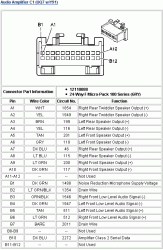
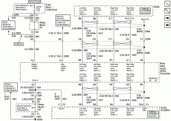
Image of the Connector chart for the Luxury amp connector #1:


Attachments

  • UQ7-Y91-Lux_Amp_Conn-1.gif
    UQ7-Y91-Lux_Amp_Conn-1.gif
    17.6 KB · Views: 5,249
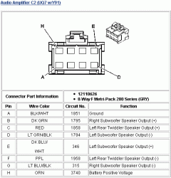
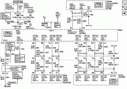
Image of the Connector chart for the Luxury amp connector #2:
 

Attachments

  • UQ7-Y91-Lux_Amp_Conn-2.gif
    UQ7-Y91-Lux_Amp_Conn-2.gif
    10.7 KB · Views: 5,146
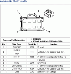
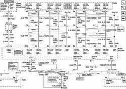
Image of the Connector chart for the Premium (Dumb) amp connector #2:
 

Attachments

  • UQ7-Prem_Dumb_Amp_Conn-2.gif
    UQ7-Prem_Dumb_Amp_Conn-2.gif
    10.3 KB · Views: 5,522
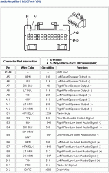
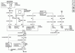
Image of the Connector chart for the Premium (Dumb) amp connector #1:
 

Attachments

  • UQ7-Prem_Dumb_Amp_Conn-1.gif
    UQ7-Prem_Dumb_Amp_Conn-1.gif
    18.2 KB · Views: 6,162
This is an OLD list (4-11-04), at this time (4-16-05), it's more of a placeholder for new part #'s, newer & and more goodies.

I will edit this with part #'s and attempt to date the entries, as I update.

Primarily INR!

Estimated Cost + 10% Pricing:

INR HU P/N:        15204334    $1625.00  Alt#: 15204335 (Both Worked)
INR-Non-Lux        15108421                    (Late `04 H2)
Amp(UM8/Y91):    15199992 - -  320.74 
GPS Antenna:      15207447 - -    45.25  ?Module? A new # is: 15135178
US/CAN DVD:      15906573 - -              DELPHI only!    Ver 5.0
Microphone:        25705367 - -    24.82
INR Manual:        15192793a  -    10.00  Order from http://www.helminc.com
                                          ----------
                                      $ 2209.25
            + Tax:
          + Shipping: 
                                          -----------
Alt Amp P/N's:        #15199992 Old Escalade amp; since replaced. Good though.                     
                              #15054675 `Heard of unconfirmed "problems" with this amp.
                              #15112662 √
                              #15054675 √
                              #15188461 √
                              #15191601 √
                              #15114454  Denali
                              #15177435 X`Was a "problem" amp.
                              #15188044 √ (OK But for "H2 ONLY") However has worked in other GM!
                              #15177435 √ (H2)
                              #15188461 X`Was a "problem" amp.
                              #15191601 √ (Not for H2)
                              #15199884


Connector on mic is:        #12052833
Mating conn. for mic:        #12085481

Connector terminals:  GM  #12020757  for 20-18 GA  New #12089649 ($8.80 /10 Bag)
                                  GM  #12020758  for larger wire.
MAC`S Electronics:        # 20101J  (From ArrivalBlue)

Micro64 Connector terminals: #15356827 Pkg of 25 (SPX- Kent Moore)

PDF Version of INR Manual
Or you can order a smaller hard copy from Helm Inc. for $10.00 Part #: 15192793a.

-------------------------------------------------------

TNR Head units:

Luxury:      10377531 - Updated#:15230099 (Confirmed)
          &    15800001
Premium &
Non-Bose: 10377287 - Updated #:
&      "    : 10351123
&      "    : 15800000
&      "    : 15229287 (05 Suburban - Premium)

05 Buick Rendezvous: 15229837 (Premium)

`05 `burb: 10333560 (Premium system)

Not confirmed Premium system TNR's:

10352578
-------------------------------------------------------

Other items (XM, Changers, OEM entertainment misc...)

XM Retrofit Kit: P/N: 12498768

XM Antennas..P/N:

'03: 15174788

'04: 15205583

The early (from an 03 H2) LUX UC6 HU part number is: 15179349. (In Dash 6-Disk HU Non-Nav). I had not found confirmation other than the reliable source.

--------------

XM parts, per Blacktrail_Av on 10-31-05:

Cable, digital radio receiver: 15172751

Cable, digital radio antenna (inline conn to antenna): 15205597

Receiver, digital radio, `must get from seperate souce. Part#: 22692861

Receiver, digital radio, kit 2007. Part# 178011509 Common accy item.

Bolt/screw, hwa for receiver bracket: 11516618 (needs 2)

Bracket, digital receiver: 15189091

Connector, Micro64 (XM main connector) GM part number 15394150

Kit with 10 leads, pins and tool J-38125-64 SPL From SPX-Kentmoore.

Cable, digital radio antenna: 15190807

Cable, digital radio antenna (rcvr to inline conn): 15205596.

Ant, digital radio (40mm high low profile antenna): 15174788

Ant,digital radio (35mm high low profile antenna):15205583
---------------

From CAFCNA: Willyt.
Ant, digital Radio and OnStar (Digital) combo "Shark Fin": 15194280  List $147.27 whosale $110.45
Cable, For dual service "sharkfin" antenna: #15292901  List $60.66  whosale $42.46.

--------------------------------

AUX harness        #15312903    $25
AUX CD changer  #15055250  $180

RSA Blank pocket: #15189381 (If you decide to remove the RSA)

--------------------------------

07 Denso nav system parts:

From tonybsr 5-11-06

15882766 Nav radio with DVD playback - Chevy GMT900
15201798 GPS Antenna
15173619 Rear View Camera
15934919 Nav Ver 2.00 DVD  DENSO ONLY!

--------------------------------

Edits: I keep adding amp P/N's!
 
Some GM Document numbers to reference:

# 1342066 Doc for speaker noise during silence.
# 813966  Doc for further testing.
# 1251531 Doc for Navigation System Description and Operation
# 1275527 Radio Theftlock Procedure
# 1261645 Nav GPS Antenna mounting loc. & Rem/Repl Procedures
# 770163  Nav Diagnostic System Check
# 798709  For VSS (DTC B0001) Checks
# 885410  Master Electrical Component List
# 857248  Entertainment Component Views
# 1193310 Splice Pack
# 851382  Remote CD Player
# 851392  Dash/Inst panel Rt-Rearview
# 851384  XM Module mount view
# 851390  RSE Assy mount (`03)
# 851380  Steering WH. Controls
# 851374  D-Pillar speaker diag.

 
GPS Antenna Installation

index.php


Photo Courtesy of CAFCNA: duramaxHD
index.php

------------------------------------------

The GPS antenna faults, operation & connection...

DTC B2462        

Circuit Description

The global positioning system (GPS) antenna is connected to the navigation radio by a coaxial cable.

Conditions for Running the DTC

The radio must detect one of the following power modes:

   * ACC
   * ON
   * RAP
   * RAP UNLK

DTC B2462 does not set if DTC B1328 or B1327 is current.

Conditions for Setting the DTC

   * The navigation radio test the GPS antenna every 0.3 second.
   * The radio determines there is an open in the GPS antenna.
   * DTC B2462 does not set if DTC B1328 or B1327 is current.

Action Taken When the DTC Sets

Unable to get GPS location updated, the radio uses the last reported position and the vehicle speed signal to calculate the vehicle position.

Route guidance may be inaccurate

This failure has no effect outside the navigation system.

Conditions for Clearing the DTC

   * A current DTC clears when the radio does not detect the failure for more than 10 seconds.
   * A history DTC clears after 50 ignition cycles with no repeat of the failure.

Diagnostic Aids

An intermittent condition may be caused by the following:

   * Mis-routed harness
   * Rubbed through wire insulation
   * Broken wire inside the insulation
 
VSS Related

------------------------------------

      The VSS wire is easy. My first time was.

  3 Head unit screws and four cluster screws (7MM head, torque them back @ 18 in pounds.) Not likely you have it already.

  Unless they banjo-stringed the connections at the rear of your HU, it should not be a problem. If that adapter is a PAC GM12 accessory aux input device, you will need to change it's power connector  wire to either battery + or the BCM's RAP source. You can cut the wire at "E" of C2 and tap it if you wish for the VSS wire, since it goes nowhere else in your truck. The adapter provides the connection so it will work with the Lux vehicles or the 05's (they have it in the harness to the connector). run the other end over to the cluster A4. Tap that wire for the VSS.

--------------------------------

What it is and what results are without a connection:

  DTC B0001 

Circuit Description

The navigation radio receives the vehicle speed signal from the PCM through a dedicated circuit shared with the instrument cluster.

Conditions for Running the DTC

    * The navigation radio must detect a power mode transition to ON.
    * The radio does not set this DTC if B1327 or B1328 is current.
    * The vehicle must drive for 4 km (2.5 mi) after receiving a GPS signal. The receipt of the GPS signal is indicated by an icon box in the upper left quadrant of the map screen with the letters GPS inside of it.

Conditions for Setting the DTC

The navigation radio compares the vehicle speed signal from the PCM to the GPS location signal every second. If the GPS signal indicates that the vehicle has traveled 4 km (2.5 mi) but no vehicle speed signal was received, the radio sets the DTC.

Action Taken When the DTC Sets

The navigation radio uses the GPS signal when the vehicle speed signal from the PCM is unavailable.

The following symptoms may happen if the vehicle speed signal from the PCM is unavailable:

    * The vehicle icon may jump to different positions on the map screen.
    * The vehicle icon, current position marker may not move on the map screen while the vehicle is being driven.
    * The route guidance accuracy may be degraded.

Conditions for Clearing the DTC

    * A current DTC clears when the navigation radio detects the vehicle speed signal from the PCM for more than one second.
    * A history DTC clears after 50 ignition cycles without a vehicle speed signal failure.

Diagnostic Aids

An intermittent condition may be caused by the following:

    * Mis-routed harness
    * Rubbed through wire insulation
    * Broken wire inside the insulation
    * A loose connector pin
----------------------------------------------------

Cluster connection diagram

This image expands; how, depends on your browser.
index.php
 
Premium Systems HU to Amp Wiring Without RSA

The image expands; how, depends on your browser.
 

Attachments

  • 840806-s.gif
    840806-s.gif
    73 KB · Views: 5,011
Luxury System Power, Noise-Cancelling mic & RSA DATA Wiring

The image expands; how, depends on your browser.
 

Attachments

  • 840712-Lux_Pwr_NoiseMic&RSA_Data.gif
    840712-Lux_Pwr_NoiseMic&RSA_Data.gif
    50.9 KB · Views: 4,896
Splice Pack SP-250 - is a shorting block for the audio accessory options: XM/DAB, RSE and an MDX (External CD Changer), However it isn't easy to access. It's normally located to the left / aside the airbag/glove box.

The images expand; how, depends on your browser.

index.php


index.php
 
CD Changer (MDX) Wiring Diagram

The image expands; how, depends on your browser.
index.php
 
XM Satellite Receiver Connections

The image expands; how, depends on your browser.
 

Attachments

  • 840821-XM.gif
    840821-XM.gif
    19.3 KB · Views: 3,196
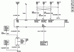
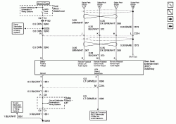
Rear Seat Entertainment (RSE) Connections

(Power & DATA)

The image expands; how, depends on your browser.
 

Attachments

  • 840823-RSE.gif
    840823-RSE.gif
    57.2 KB · Views: 3,283
Back
Top