
itsstopher
PM 2018
PM 2017
PM 2016
PM 2015
PM 2014
PM 2013
PM 2012
SM 2011
SM 2010
SM 2009
SM 2008
SM 2007
SM 2006
SM 2005
SM 2004
SM 2003
Full Member
Removal Procedure

1. Raise and support the vehicle.
2. Support the rear axle.
3. Disconnect the electronic suspension control (ESC) sensor, if equipped.
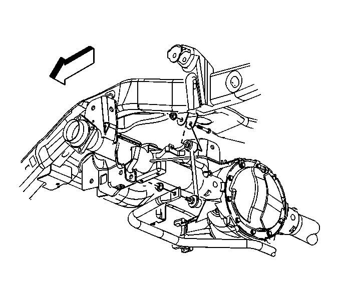
4. Remove the stabilizer shaft link retaining nut from the frame.
5. Remove the lower shock absorber nut and bolt from the rear axle.
6. Lower the rear axle until the springs are fully unloaded.
7. Remove the coil spring and the upper insulator.
Installation Procedure
1. Install the coil spring and the upper insulator.
2. Raise the rear axle.
Notice
Use the correct fastener in the correct location. Replacement fasteners must be the correct part number for that application. Fasteners requiring replacement or fasteners requiring the use of thread locking compound or sealant are identified in the service procedure. Do not use paints, lubricants, or corrosion inhibitors on fasteners or fastener joint surfaces unless specified. These coatings affect fastener torque and joint clamping force and may damage the fastener. Use the correct tightening sequence and specifications when installing fasteners in order to avoid damage to parts and systems.
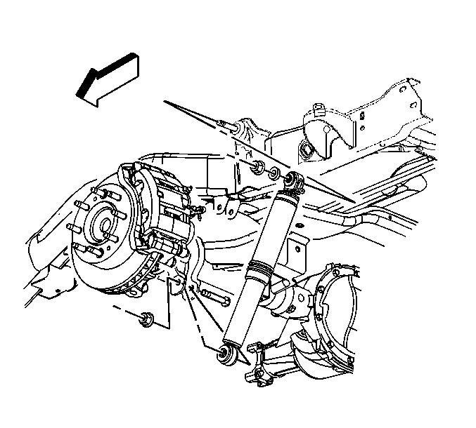
3. Install the lower shock absorber retaining nut and bolt to the rear axle. Tighten
the lower shock absorber retaining nut and bolt to 95 N?m (70 lb ft).
4. Install the stabilizer shaft link to the frame.
5. Install the stabilizer shaft link retaining nut. Tighten
the stabilizer shaft link retaining nut to 65 N?m (48 lb ft).
6. Connect the electronic suspension control (ESC) sensor, if equipped.
7. Remove the rear axle support.
8. Lower the vehicle.
1. Raise and support the vehicle.
2. Support the rear axle.
3. Disconnect the electronic suspension control (ESC) sensor, if equipped.
4. Remove the stabilizer shaft link retaining nut from the frame.
5. Remove the lower shock absorber nut and bolt from the rear axle.
6. Lower the rear axle until the springs are fully unloaded.
7. Remove the coil spring and the upper insulator.
Installation Procedure
1. Install the coil spring and the upper insulator.
2. Raise the rear axle.
Notice
Use the correct fastener in the correct location. Replacement fasteners must be the correct part number for that application. Fasteners requiring replacement or fasteners requiring the use of thread locking compound or sealant are identified in the service procedure. Do not use paints, lubricants, or corrosion inhibitors on fasteners or fastener joint surfaces unless specified. These coatings affect fastener torque and joint clamping force and may damage the fastener. Use the correct tightening sequence and specifications when installing fasteners in order to avoid damage to parts and systems.
3. Install the lower shock absorber retaining nut and bolt to the rear axle. Tighten
the lower shock absorber retaining nut and bolt to 95 N?m (70 lb ft).
4. Install the stabilizer shaft link to the frame.
5. Install the stabilizer shaft link retaining nut. Tighten
the stabilizer shaft link retaining nut to 65 N?m (48 lb ft).
6. Connect the electronic suspension control (ESC) sensor, if equipped.
7. Remove the rear axle support.
8. Lower the vehicle.