
-
If you currently own, previously owned or want to own an Avalanche, we welcome you to become a member today. Membership is FREE, register now!
You are using an out of date browser. It may not display this or other websites correctly.
You should upgrade or use an alternative browser.
You should upgrade or use an alternative browser.
Engine External Components R&R Instructions
- Thread starter sperry
- Start date
5.3 6.0 Air Induction Components Location
(1) Clamp
(2) Air Duct
(3) Clamp
(4) Intake Air Temperature (IAT)/Mass Air Flow (MAF) Sensor
(5) Air Cleaner Assembly
(6) Air Restriction Indicator
The image expands; how, depends on your browser
(1) Clamp
(2) Air Duct
(3) Clamp
(4) Intake Air Temperature (IAT)/Mass Air Flow (MAF) Sensor
(5) Air Cleaner Assembly
(6) Air Restriction Indicator
The image expands; how, depends on your browser
Attachments
Heated O2 Sensor Location 5.3L
(1) Bank 1 Sensor 2 HO2S
(2) Bank 1 Sensor 1 HO2S
(3) Bank 1 Sensor 1 HO2S Threaded Boss
(4) Left Bank Catalytic Convertor
(5) Bank 1 Sensor 2 HO2S Threaded Boss
(6) Bank 2 Sensor 1 HO2S Threaded Boss
(7) Right Side Frame Rail
(8} Right Bank Catalytic Convertor
(9) Bank 2 Sensor 2 HO2S Threaded Boss
(10) Bank 2 Sensor 2 HO2S
(11) Bank 2 Sensor 1 HO2S
The image expands; how, depends on your browser
Attachments
Heated Oxygen Sensors (HO2S) 6.0L
(1) Bank 2 Sensor 1 HO2S
(2) Bank 1 Sensor 2 HO2S Threaded Boss
(3) Right Side Frame Rail
(4) Right Bank Catalytic Convertor
(5) Bank 2 Sensor 2 HO2S
(6) Bank 2 Sensor 2 HO2S Threaded Boss
(7) Left Bank Catalytic Convertor
(8} Bank 1 Sensor 2 HO2S
(9) Bank 1 Sensor 1 HO2S Threaded Boss
(10) Bank 1 Sensor 1 HO2S
(11) Bank 2 Sensor 1 HO2S Threaded Boss
The image expands; how, depends on your browser
Attachments


8.1L Camshaft Position (CMP) Sensor Replacement
Removal Procedure

1. Raise and suitably support the vehicle. Refer to Lifting and Jacking the Vehicle in General Information.
2. If the vehicle is equipped with the underbody shield package, remove the steering linkage shield.
3. Disconnect the camshaft position (CMP) sensor electrical connector (3).
4. Remove the CMP sensor bolt (2).
5. Remove the CMP sensor (1).
6. Inspect the CMP sensor for wear, cracks or leakage if the sensor is not being replaced.
Installation Procedure
Important
Inspect the CMP sensor O-ring for wear or damage. If a problem is found, replace the O-ring. Lubricate the new O-ring with engine oil before installing.
1. Install the CMP sensor (1).
Notice
Use the correct fastener in the correct location. Replacement fasteners must be the correct part number for that application. Fasteners requiring replacement or fasteners requiring the use of thread locking compound or sealant are identified in the service procedure. Do not use paints, lubricants, or corrosion inhibitors on fasteners or fastener joint surfaces unless specified. These coatings affect fastener torque and joint clamping force and may damage the fastener. Use the correct tightening sequence and specifications when installing fasteners in order to avoid damage to parts and systems.
Important
The CMP sensor bolt has self-tapping threads, care must be taken, NOT to strip the threads when installing.
2. Install the CMP sensor bolt (2).
Tighten
Tighten the bolt to 12N?m(106 lb in).
3. Connect the CMP sensor electrical connector (3).
4. Install the steering linkage shield, if equipped.
5. Lower the vehicle.
Removal Procedure
1. Raise and suitably support the vehicle. Refer to Lifting and Jacking the Vehicle in General Information.
2. If the vehicle is equipped with the underbody shield package, remove the steering linkage shield.
3. Disconnect the camshaft position (CMP) sensor electrical connector (3).
4. Remove the CMP sensor bolt (2).
5. Remove the CMP sensor (1).
6. Inspect the CMP sensor for wear, cracks or leakage if the sensor is not being replaced.
Installation Procedure
Important
Inspect the CMP sensor O-ring for wear or damage. If a problem is found, replace the O-ring. Lubricate the new O-ring with engine oil before installing.
1. Install the CMP sensor (1).
Notice
Use the correct fastener in the correct location. Replacement fasteners must be the correct part number for that application. Fasteners requiring replacement or fasteners requiring the use of thread locking compound or sealant are identified in the service procedure. Do not use paints, lubricants, or corrosion inhibitors on fasteners or fastener joint surfaces unless specified. These coatings affect fastener torque and joint clamping force and may damage the fastener. Use the correct tightening sequence and specifications when installing fasteners in order to avoid damage to parts and systems.
Important
The CMP sensor bolt has self-tapping threads, care must be taken, NOT to strip the threads when installing.
2. Install the CMP sensor bolt (2).
Tighten
Tighten the bolt to 12N?m(106 lb in).
3. Connect the CMP sensor electrical connector (3).
4. Install the steering linkage shield, if equipped.
5. Lower the vehicle.
Crankshaft Position (CKP) Sensor Replacement 8.1L
Removal Procedure
Notice
In order to prevent damage to the crankshaft position sensor reluctor wheel/ring care must be used when removing or installing this component.

1. Raise and suitably support the vehicle. Refer to Lifting and Jacking the Vehicle.
2. Remove the fuel line bracket nut (5).
3. Remove the fuel line bracket from the bellhousing stud.
4. Lower the vehicle.

5. Remove the driver side rear ignition coil bolts.
6. Reposition the coil.
7. Disconnect the crankshaft position (CKP) sensor electrical connector.
8. Use penetrating oil and allow the oil to soak around the CKP sensor prior to removing the sensor.
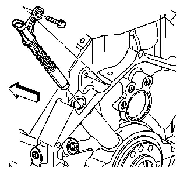
9. Remove the CKP sensor bolt.
10. Prior to removal of the CKP sensor, twist the sensor back and forth.
11. Remove the CKP sensor.

12. Inspect the CKP sensor for wear.
Important
The CKP sensor is designed to contact the reluctor wheel of the crankshaft. Wear may be noticeable on the end of the sensor.
13. Normal CKP sensor wear will be shown on the wear strips (1), and no wear will be shown on the sensor sensing element (2).
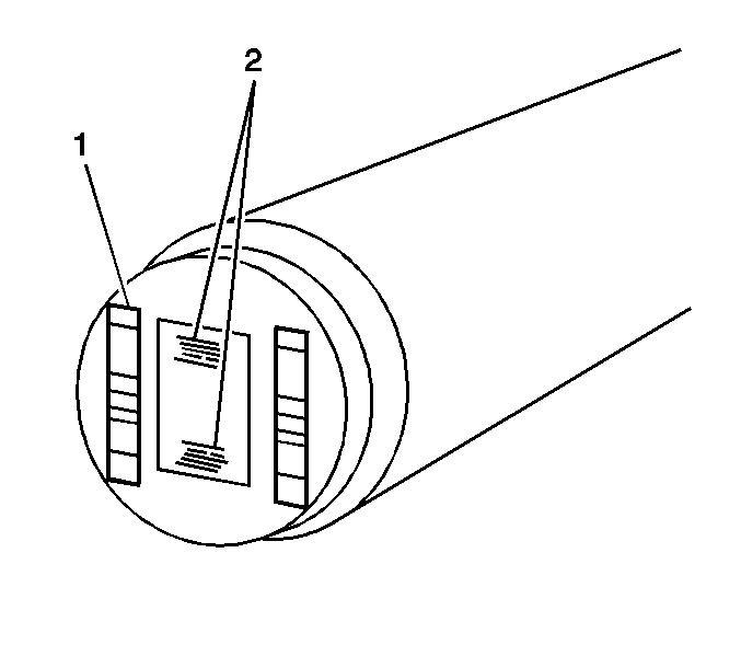
14. Excessive or abnormal sensor wear will be shown on the sensing element (2).
15. If excessive/abnormal wear is present, replace the sensor.
-----------
Note Per CAFCNA Member "Durwin" on 1-12-07: 'The GM part number for the Crankshaft Position Sensor for the 02 Avalanche with the 8.1L engine.
The old number 12576123, has been revised to 12575172
-----------
Installation Procedure
1. If reusing the old sensor, Inspect the O-rings for cuts, cracks, tears or damage, replace as needed.
2. Lubricate the CKP sensor O-rings with clean engine oil.
Important
Ensure that the CKP sensor is fully seated against the crankshaft reluctor ring. The upper flange on the sensor MAY NOT seat against the engine block.
3. Install the CKP sensor.
Important
The CKP sensor bolt has adhesive applied to the threads. The adhesive may have come off during removal of the bolt. Ensure that the bolt hole is clean of any debris before installing the reinstalling bolt.
4. If reusing the old sensor, apply thread adhesive GM P/N United States 12345493, GM P/N Canada 10953488, or equivalent to the bolt threads.
Notice
Use the correct fastener in the correct location. Replacement fasteners must be the correct part number for that application. Fasteners requiring replacement or fasteners requiring the use of thread locking compound or sealant are identified in the service procedure. Do not use paints, lubricants, or corrosion inhibitors on fasteners or fastener joint surfaces unless specified. These coatings affect fastener torque and joint clamping force and may damage the fastener. Use the correct tightening sequence and specifications when installing fasteners in order to avoid damage to parts and systems.
5. Install the CKP sensor bolt.
Tighten
Tighten the bolt to 12 N?m (106 lb in).
[/img]
6. Connect the CKP sensor electrical connector.
7. Position the coil to the rocker cover.
8. Install the driver side rear ignition coil bolts.
Tighten
Tighten the bolts to 12 N?m (106 lb in).
9. Raise the vehicle.
10. Install the fuel line bracket to the bellhousing stud.
11. Install the fuel line bracket nut (5).
12. Lower the vehicle.
13. Perform the CKP system variation learn procedure.
-------
Removal Procedure
Notice
In order to prevent damage to the crankshaft position sensor reluctor wheel/ring care must be used when removing or installing this component.
1. Raise and suitably support the vehicle. Refer to Lifting and Jacking the Vehicle.
2. Remove the fuel line bracket nut (5).
3. Remove the fuel line bracket from the bellhousing stud.
4. Lower the vehicle.
5. Remove the driver side rear ignition coil bolts.
6. Reposition the coil.
7. Disconnect the crankshaft position (CKP) sensor electrical connector.
8. Use penetrating oil and allow the oil to soak around the CKP sensor prior to removing the sensor.
9. Remove the CKP sensor bolt.
10. Prior to removal of the CKP sensor, twist the sensor back and forth.
11. Remove the CKP sensor.
12. Inspect the CKP sensor for wear.
Important
The CKP sensor is designed to contact the reluctor wheel of the crankshaft. Wear may be noticeable on the end of the sensor.
13. Normal CKP sensor wear will be shown on the wear strips (1), and no wear will be shown on the sensor sensing element (2).
14. Excessive or abnormal sensor wear will be shown on the sensing element (2).
15. If excessive/abnormal wear is present, replace the sensor.
-----------
Note Per CAFCNA Member "Durwin" on 1-12-07: 'The GM part number for the Crankshaft Position Sensor for the 02 Avalanche with the 8.1L engine.
The old number 12576123, has been revised to 12575172
-----------
Installation Procedure
1. If reusing the old sensor, Inspect the O-rings for cuts, cracks, tears or damage, replace as needed.
2. Lubricate the CKP sensor O-rings with clean engine oil.
Important
Ensure that the CKP sensor is fully seated against the crankshaft reluctor ring. The upper flange on the sensor MAY NOT seat against the engine block.
3. Install the CKP sensor.
Important
The CKP sensor bolt has adhesive applied to the threads. The adhesive may have come off during removal of the bolt. Ensure that the bolt hole is clean of any debris before installing the reinstalling bolt.
4. If reusing the old sensor, apply thread adhesive GM P/N United States 12345493, GM P/N Canada 10953488, or equivalent to the bolt threads.
Notice
Use the correct fastener in the correct location. Replacement fasteners must be the correct part number for that application. Fasteners requiring replacement or fasteners requiring the use of thread locking compound or sealant are identified in the service procedure. Do not use paints, lubricants, or corrosion inhibitors on fasteners or fastener joint surfaces unless specified. These coatings affect fastener torque and joint clamping force and may damage the fastener. Use the correct tightening sequence and specifications when installing fasteners in order to avoid damage to parts and systems.
5. Install the CKP sensor bolt.
Tighten
Tighten the bolt to 12 N?m (106 lb in).
6. Connect the CKP sensor electrical connector.
7. Position the coil to the rocker cover.
8. Install the driver side rear ignition coil bolts.
Tighten
Tighten the bolts to 12 N?m (106 lb in).
9. Raise the vehicle.
10. Install the fuel line bracket to the bellhousing stud.
11. Install the fuel line bracket nut (5).
12. Lower the vehicle.
13. Perform the CKP system variation learn procedure.
-------
CKP System Variation Learn Procedure
Important
For additional diagnostic information, refer to DTC P1336 .
1. Install a scan tool.
2. With a scan tool, monitor the powertrain control module for DTCs. If other DTCs are set, except DTC P1336, refer to Diagnostic Trouble Code (DTC) List for the applicable DTC that set.
3. With a scan tool, select the crankshaft position variation learn procedure.
4. Observe the fuel cut-off for the engine that you are performing the learn procedure on.
5. The scan tool instructs you to perform the following items:
* Block the drive wheels.
* Apply the vehicles parking brake.
* Cycle the ignition from OFF to ON.
* Apply and hold the brake pedal.
* Start and idle the engine.
* Turn OFF the A/C.
* Place the vehicles transmission in Park (A/T) or Neutral (M/T).
* The scan tool monitors certain component signals to determine if all the conditions are met to continue with the procedure. The scan tool only displays the condition that inhibits the procedure. The scan tool monitors the following components:
o Crankshaft position (CKP) sensors activity--If there is a CKP sensor condition, refer to the applicable DTC that set.
o Camshaft position (CMP) sensor activity--If there is a CMP sensor condition, refer to the applicable DTC that set.
o Engine coolant temperature (ECT)--If the engine coolant temperature is not warm enough, idle the engine until the engine coolant temperature reaches the correct temperature.
6. With the scan tool, enable the crankshaft position system variation learn procedure.
Important
While the learn procedure is in progress, release the throttle immediately when the engine starts to decelerate. The engine control is returned to the operator and the engine responds to throttle position after the learn procedure is complete.
7. Slowly increase the engine speed to the RPM that you observed.
8. Immediately release the throttle when fuel cut-off is reached.
9. The scan tool displays Learn Status: Learned this ignition. If the scan tool does NOT display this message and no additional DTCs set, refer to Symptoms - Engine Mechanical in Engine Mechanical. If a DTC set, refer to Diagnostic Trouble Code (DTC) List for the applicable DTC that set.
10. Turn OFF the ignition for 30 seconds after the learn procedure is completed successfully.
Important
For additional diagnostic information, refer to DTC P1336 .
1. Install a scan tool.
2. With a scan tool, monitor the powertrain control module for DTCs. If other DTCs are set, except DTC P1336, refer to Diagnostic Trouble Code (DTC) List for the applicable DTC that set.
3. With a scan tool, select the crankshaft position variation learn procedure.
4. Observe the fuel cut-off for the engine that you are performing the learn procedure on.
5. The scan tool instructs you to perform the following items:
* Block the drive wheels.
* Apply the vehicles parking brake.
* Cycle the ignition from OFF to ON.
* Apply and hold the brake pedal.
* Start and idle the engine.
* Turn OFF the A/C.
* Place the vehicles transmission in Park (A/T) or Neutral (M/T).
* The scan tool monitors certain component signals to determine if all the conditions are met to continue with the procedure. The scan tool only displays the condition that inhibits the procedure. The scan tool monitors the following components:
o Crankshaft position (CKP) sensors activity--If there is a CKP sensor condition, refer to the applicable DTC that set.
o Camshaft position (CMP) sensor activity--If there is a CMP sensor condition, refer to the applicable DTC that set.
o Engine coolant temperature (ECT)--If the engine coolant temperature is not warm enough, idle the engine until the engine coolant temperature reaches the correct temperature.
6. With the scan tool, enable the crankshaft position system variation learn procedure.
Important
While the learn procedure is in progress, release the throttle immediately when the engine starts to decelerate. The engine control is returned to the operator and the engine responds to throttle position after the learn procedure is complete.
7. Slowly increase the engine speed to the RPM that you observed.
8. Immediately release the throttle when fuel cut-off is reached.
9. The scan tool displays Learn Status: Learned this ignition. If the scan tool does NOT display this message and no additional DTCs set, refer to Symptoms - Engine Mechanical in Engine Mechanical. If a DTC set, refer to Diagnostic Trouble Code (DTC) List for the applicable DTC that set.
10. Turn OFF the ignition for 30 seconds after the learn procedure is completed successfully.
Document ID# 871500
2003 Chevrolet Avalanche
2003 Chevrolet Avalanche
DTC P0327 or P0332 5.3 referenced.
Circuit Description
The knock sensor (KS) system enables the powertrain control module (PCM) to control the ignition timing for the best possible performance while protecting the engine from potentially damaging levels of detonation. The system uses two KS located under the intake manifold. KS 1 is located at the front of the engine. KS 2 is located at the back of the engine. Each KS produces an AC voltage that varies depending on the vibration level during engine operation. The PCM adjusts the spark timing based on the amplitude and frequency of the KS signal. The PCM receives a signal from each KS through a signal circuit. The KS ground is supplied by the engine block through the sensor housing. The PCM uses each KS signal to calculate an average voltage range value. If the KS system is operating normally, the PCM should monitor the KS voltage varying above and below the voltage range. If the PCM detects the KS signal voltage within the voltage range, or the KS signal is not present, a DTC will set. DTC P0327 refers to the front KS. DTC P0332 refers to the rear KS.
Conditions for Running the DTC
* DTCs P0117, P0118, or P0125 are not set.
* The minimum noise level must be learned. The minimum noise level is learned when the following conditions are met:
■ The engine coolant temperature (ECT) must be greater than 60?C (140?F).
■ The engine speed is between 475-975 RPM for 10 seconds.
* The engine speed is between 1,500-3,000 RPM.
* The manifold absolute pressure (Map) is less than 49 kPa.
* The engine coolant temperature (ECT) is more than 60?C (140?F).
* The throttle angle is more than 0 percent.
* The engine run time is more than 10 seconds.
* The ignition voltage is more than 10 volts.
Conditions for Setting the DTC
* The PCM detects that the KS signal is within the calculated voltage range or the KS signal is not present.
* The above conditions are met for more than 9 seconds.
Action Taken When the DTC Sets
* The control module illuminates the malfunction indicator lamp (MIL) on the second consecutive ignition cycle that the diagnostic runs and fails.
* The control module records the operating conditions at the time the diagnostic fails. The first time the diagnostic fails, the control module stores this information in the Failure Records. If the diagnostic reports a failure on the second consecutive ignition cycle, the control module records the operating conditions at the time of the failure. The control module writes the operating conditions to the Freeze Frame and updates the Failure Records.
Conditions for Clearing the MIL/DTC
* The control module turns OFF the malfunction indicator lamp (MIL) after 3 consecutive ignition cycles that the diagnostic runs and does not fail.
* A current DTC, Last Test Failed, clears when the diagnostic runs and passes.
* A history DTC clears after 40 consecutive warm-up cycles, if no failures are reported by this or any other emission related diagnostic.
* Clear the MIL and the DTC with a scan tool.
Diagnostic Aids
* If DTCs P0327 and P0332 are set at the same time, inspect for poor connections at the KS harness jumper, located at the left rear side of the intake manifold.
* Inspect the KS for physical damage. A KS that is dropped or damaged may cause a DTC to set.
* Inspect the KS for proper installation. A KS that is loose or over torqued may cause a DTC to set. The KS should be free of thread sealant. The KS mounting surface should be free of burrs, casting flash, and foreign material.
* For an intermittent condition, refer to Intermittent Conditions .
Test Description
The numbers below refer to the step numbers on the diagnostic table.
2. This step ensures that the malfunction is present.
3. This step tests the KS and the KS jumper harness for an open or a short to ground.
4. Tapping on the engine block will simulate an engine knock.
Loggie
Charter Member
PM 2023
PM 2021
PM 2020
PM 2019
PM 2018
PM 2017
PM 2016
PM 2015
PM 2014
PM 2013
PM 2012
SM 2011
SM 2010
SM 2009
SM 2008
SM 2007
SM 2006
SM 2005
SM 2004
SM 2003
Full Member
Good info for new folks to look over