• If you currently own, previously owned or want to own an Avalanche, we welcome you to become a member today. Membership is FREE, register now!

Locking Differential Disassembled Views and R&R (02 Ref)

itsstopher

PM 2018
PM 2017
PM 2016
PM 2015
PM 2014
PM 2013
PM 2012
SM 2011
SM 2010
SM 2009
SM 2008
SM 2007
SM 2006
SM 2005
SM 2004
SM 2003
Full Member
Joined
Sep 2, 2004
Messages
5,470
Location
Gilford New Hampshire
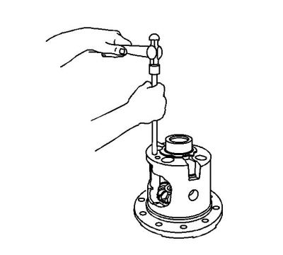
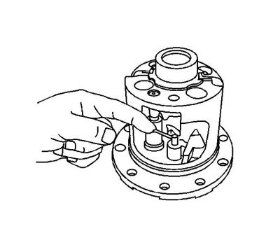
8.6 Inch Locking Differential

(1) Differential Pinion Gear Shaft
(2) Differential Case
(3) Differential Pinion Gear Shaft Lock Bolt
(4) Locking Differential Lockout Bushings
(5) Locking Differential Clutch Disc Thrust Washer
(6) Locking Differential Clutch Disc Guide
(7) Locking Differential Clutch Disc Set
(8 ) Differential Pinion Gear Thrust Washer
(9) Differential Pinion Gear
(10) Locking Differential Side Gear
(11) Locking Differential Thrust Block
(12) Differential Pinion Gear
(13) Differential Pinion Gear Thrust Washer
(14) Locking Differential Side Gear, Cam-Faced
(15) Locking Differential Cam
(16) Locking Differential Governor
(17) Wave Washer
(1:cool: Locking Differential Clutch Disc Set
(19) Locking Differential Clutch Disc Guide
(20) Locking Differential Snap Ring Retainer
(21) Locking Differential Clutch Disc Thrust Washer

Bigger Pic

8.6lock.JPG


9.5 Locking Differential

(1) Differential Case
(2) Differential Pinion Gear Shaft
(3) Locking Differential Lockout Bushing
(4) Differential Pinion Gear Shaft Lock Bolt
(5) Locking Differential Clutch Disc Thrust Washer
(6) Locking Differential Clutch Disc Set
(7) Locking Differential Clutch Disc Guide
(8 ) Locking Differential Side Gear
(9) Differential Pinion Gear Thrust Washer
(10) Differential Pinion Gear
(11) Locking Differential Governor
(12) Locking Differential Latching Bracket
(13) Locking Differential Thrust Block
(14) Differential Pinion Gear Thrust Washer
(15) Differential Pinion Gear
(16) Locking Differential Side Gear, Cam-Faced
(17) Locking Differential Cam
(1:cool: Wave Washer
(19) Locking Differential Clutch Disc Guide
(20) Locking Differential Clutch Disc Set
(21) Locking Differential Side Gear Thrust Sleeve
(22) Differential Side Gear Shim

Bigger Pic

9.5lock.JPG

 
10.5 Locking Differential

(1) Differential
(2) Differential Ring Gear Bolt
(3) Locking Differential Governor
(4) Locking Differential Governor
(5) Locking Differential Clutch Disc Thrust Washer
(6) Locking Differential Side Gear Thrust Sleeve
(7) Locking Differential Clutch Disc Guide
(8 ) Locking Differential Clutch Disc Set
(9) Locking Differential Cam
(10) Locking Differential Side Gear
(11) Differential Pinion Gear Thrust Washer
(12) Differential Pinion Gear
(13) Locking Differential Thrust Block
(14) Locking Differential Thrust Block Washer
(15) Locking Differential Spider
(16) Locking Differential Thrust Block Washer
(17) Locking Differential Thrust Block
(1:cool: Locking Differential Side Gear
(19) Locking Differential Clutch Disc Guide
(20) Locking Differential Clutch Disc Set
(21) Differential Side Gear Shim

Bigger Pic

10.5lock.JPG

 
Locking Differential Disassemble 8.6, 9.5 Inch Axles

Tools Required
J 26252 Locking Differential Governor Remover

normal_J26252.JPG


1. Remove the ring gear, if necessary.

normal_locdif1.JPG


2. Remove the governor bushing using the J 26252 .
3. Remove the governor assembly. To aid in the removal of the governor assembly, turn the side gear as necessary to position the governor  assembly between two of the side gear teeth.

normal_locdif2.JPG


4. Remove the latching bracket assembly bushing using the J 26252 . To aid in the removal of the latching bracket assembly, turn the side gear as necessary to position the latching bracket assembly between two of the side gear teeth.
5. Remove the pinion shaft lock bolt.
6. Remove the pinion shaft.
7. Remove the differential pinion gears and the thrust washers. Rotate the pinion gears and roll the pinion gears and the thrust washers out of the case through the differential window. Mark the pinion gears and thrust washers accordingly for re-assembly.
8. Remove the thrust block.
9. Remove the right side gear and clutch disc assembly.
10. Remove the right side shim.

normal_locdif3.JPG


11. Remove the left side gear cam unit and clutch disc assembly.

normal_locdif4.JPG


12. Remove the left side gear thrust washer.


Locking Differential Assemble 8.6, 9.5 Inch Axles


Important

The left and right side gear backlash and thrust block thickness measurement must be completed before the components of the locking differential can be assembled.


normal_locdif4.JPG


1. Install the left side gear thrust washer.

normal_locdif3.JPG


2. Install the left side gear cam unit and clutch disc assembly.
3. Install the right side gear thrust washer.
4. Install the right side clutch pack assembly.
5. Install the right side gear.


Important

If the original pinion gears and thrust washers are being re-used, install the pinion gears and thrust washers on the same side as when removed.


6. Install the pinion gear and the pinion thrust washers. Place the pinion gears and the pinion thrust washers 180 degrees apart.
7. Rotate the pinion gears and the pinion thrust washers 90 degrees and align the pinion gears with the pinion shaft opening in the differential case.
8. Install the thrust block. The open side of the thrust block must face the window opening.
9. Install the pinion shaft.
10. Install the new pinion shaft lock bolt. Tighten the pinion shaft lock bolt finger tight.

normal_locdif5.JPG


11. Install the governor assembly.
12. Install the governor bushing using a hammer and a brass drift.

Specifications
Press the bushing into place until there is 0.025-0.076 mm (0.010-0.030 in) of shaft end play.

normal_locdif6.JPG


13. Install the latching bracket assembly. The straight end of the latching bracket spring must be over and outside the governor assembly shaft.
14. Install the latching bracket bushing using a hammer and a brass drift.

Specifications
Press the bushing into place until there is 0.000-0.051 mm (0.000-0.002 in) of shaft end play.

15. Tighten the pinion shaft lock bolt.

Tighten
Tighten the pinion shaft lock bolt to 36 N?m (27 lb ft).

16. Install the ring gear, if necessary.


Back
Top