• If you currently own, previously owned or want to own an Avalanche, we welcome you to become a member today. Membership is FREE, register now!

NO-FRILLS AUX. input for $3.00

Just did this to my Dmaxalanche  loving it. I just cut  the left and right positives , taped into the black white . Behind the glove box

Never going to use XM anyways, I didnt instal the antena while building the truck
 
Connector Part Information     ? 12064799
    ? 12-Way F Micro-Pack 100 Series (BK)

Pin Wire Color Circuit No. Function
A-B -- -- Not Used
C BARE 1573 Drain Wire (w/ U2K/U2L)
D -- -- Not Used
E D GN/WH 817 Vehicle Speed Signal (w/ Y91)
F-G -- -- Not Used
H D GN/WH 368 Remote Playback Device Right Audio Signal (w/ U2K/U2L)
J BN/WH 367 Remote Playback Device Left Audio Signal (w/ U2K/U2L)
K BK/WH 372 Remote Playback Device Common Audio Signal (w/ U2K/U2L)
L OG/BK 2061 Cellular Telephone Voice Low Reference
M PK/BK 2062 Cellular Telephone Voice Signal
 

Attachments

  • c2rado0306.png
    c2rado0306.png
    3.5 KB · Views: 303
Help Help, the images are gone of the connections to make.  Brn/Wht Grn/Wht wires go where? and what do
you do with the Blk/Wht wire? help help.
 
It appears the OP or anyone else from early on isn't going to fix the pics, links.  I was able to get mine wired up based on what "ohiobellboy" posted on page 10 of this thread in post #243.

His reply is the next best thing to a picture. Good luck.
 
magnetb0y said:
Help Help, the images are gone of the connections to make.  Brn/Wht Grn/Wht wires go where? and what do
you do with the Blk/Wht wire? help help.


mattt said:
It appears the OP or anyone else from early on isn't going to fix the pics, links.  I was able to get mine wired up based on what "ohiobellboy" posted on page 10 of this thread in post #243.

His reply is the next best thing to a picture. Good luck.

Sorry guys, the pix I have are watermarked to another site and I can't post them here.
 
ohiobellboy said:
Sorry guys, the pix I have are watermarked to another site and I can't post them here.

Do you want me to do it. LOL
 
ohiobellboy said:
Sorry guys, the pix I have are watermarked to another site and I can't post them here.

Can you upload them to imgur or photobucket? And post a link?
 
Bose system has a sub.

On another note....I've had mine working for a while now. One thing I've noticed.....with the volume at about 3/4 on the ipod, the volume output from the car stereo is considerably lower than any other source from the car stereo.  What I mean is when I'm on the tuner or listening to a CD, the volume is considerably higher vs. having the ipod wired in as detailed in this thread.  When listening to a CD or the radio, I generally have this car stereo volume around the half mark.  When listening to the ipod plugged in to the jack, the half mark is way too low, volume wise.

Is this just the nature of the beast or is there some adjustment I should make to have the various source volumes all be equal?
 
mattt said:
Bose system has a sub.

On another note....I've had mine working for a while now. One thing I've noticed.....with the volume at about 3/4 on the ipod, the volume output from the car stereo is considerably lower than any other source from the car stereo.  What I mean is when I'm on the tuner or listening to a CD, the volume is considerably higher vs. having the ipod wired in as detailed in this thread.  When listening to a CD or the radio, I generally have this car stereo volume around the half mark.  When listening to the ipod plugged in to the jack, the half mark is way too low, volume wise.

Is this just the nature of the beast or is there some adjustment I should make to have the various source volumes all be equal?


Mine is the same,

I got a call while plugged in, worked hands free fairly well
 
I completed this tremendous and ridiculously cheap $3 mod the other day and it works perfectly. This is a great mod for anyone with an older vehicle, with XM, that does not have an audio jack built in for connecting external audio devices.

I would like to share a few things I learned along the way.  First, as others have noted, many of the original schematics, diagrams and/or pictures are no longer in this thread,  Therefore I created/reproduced similar ones and they are included below.  Note: The following applies to a 2004 Avalanche Z71 with a factory Bose sound system, 6 CD player and XM receiver. 

1. I made my connections behind the radio after removing it.  As noted in prior posts, the connections can be made instead at the XM receiver located behind the glove box.  If you choose this route, you will have to remove the small blue lock tab from behind the jack that plugs into the left side of the XM unit in order to remove the cable harness.  See photo below for XM unit and blue tab.  When you plug the harness back in you don?t need to use the blue lock tab again, the XM jack will lock in without it.

2. I used Cat5 cable (8 wires) which, if you leave the outer jacket on, can be confusing sorting out the correct wire colors (on the other end) after soldering the 5 needed to the audio jack.  Maybe my old eyes aren?t what they used to be.

3. Soldering is the only method for connecting the wires between the jack and radio head. Anything less will be unreliable.  Put a small towel or rag on the lower radio shelf and drape it over the climate controls below.  Prevents scratches and any hot solder falling where you don?t want it.

4. I?m not sure if it is necessary to disconnect the battery to prevent the radio anti-theft feature from kicking in.  I did to be on the safe side and to prevent it from draining.

5. After the mod was completed, I noticed a barely imperceptible level of XM audio bleeding through, at a very high volume setting, when the radio was tuned to XM with my Android connected to the audio jack but not on.  The display on the radio said ?Preview? rather than the desired ?No Signal?.  Double checked everything visually and with an OHM meter, nothing amiss.  Disconnected the XM audio wires from pins 3 & 4 on the audio jack, did not help.  Solution, disconnect the XM aerial from the XM receiver.  See picture below.

6. Regarding the two black wires noted in prior posts.  My first attempt to eliminate the XM bleed through (# 5 above) was to connect Pin 1 to the other black wire (really a bare wire covered in black tape).  Made not an iota of difference in sound quality or eliminating the XM bleed through.  For what?s it worth.

Thanks to everyone who contributed to this thread.  Special thanks to Jaywyatt for the original idea.  Hope what I added helps.

Retired guy,
 

Attachments

  • Phone Jack Pic & Connections.jpg
    Phone Jack Pic & Connections.jpg
    73.6 KB · Views: 242
  • Radio-XM Schematic.jpg
    Radio-XM Schematic.jpg
    46.8 KB · Views: 241
  • Radio Plug.jpg
    Radio Plug.jpg
    60.2 KB · Views: 239
  • XM Radio Receiver.jpg
    XM Radio Receiver.jpg
    59.2 KB · Views: 238
Thanks for the info.  (y)

Do you use XM. ??
 
MS03 2500 said:
Thanks for the info.  (y)

Do you use XM. ??

Only when it was a free 6 month trial way back when I bought my A/V.  My 10 year old A/V just broke 50K miles, I bought it in Feb. 06 when it had 25K miles.  So in the 8 years I had it, I only added 25K.  Obviously I'm not in my A/V enough to justify the XM monthly subscription.

Besides I'm quite satisfied with streaming internet FM both on my home computer and now in my A/V - and it's free.  If I ever want XM (very unlikely) all I have to do is plug the XM aerial back in.

Best, retired guy. 
 
I will be doing this mod shortly but I will be doing it a little differently than others seem to have done it here.

I will probably pull mine from behind the Glove box.

I will wire mine to have a male and female plug so I can just plug them together to go back to factory.

I will do this in this manner so I can build different harnesses to do what I want.

Eventually I will have a CarPC using this as the input to the Radio and have the XM feed either into the computer or have a relay on the lines to go between the XM and computer.

Any additional audio inputs would go to the computer directly.

Rodney
 
I just dropped my glove box and saw the unit behind there.. Wow, will literally take me about 10 minutes to make the adapter I want to make. Will take longer for me to switch from solder to heat gun to shrink the protective tubing I will need.

Does anyone know what the Orange and Green wires are?

I have an '03 and mine looks a little different. The top connector is the same but the bottom connector has a blue plug with two "things" on it. They look almost like fiber optic cables instead of wires but I suppose they could be coaxial wires.

I do NOT have On* on my truck. Just XM radio with the in dash 6 disk changer.

I also have heard conflicting black and wires to use... I stripped the protective outer tape off mine and the brown/white and green/white wires are bundled with the "inside" or higher of the two black/white wires on the plug. Someone else had stated to use the bottom black/white wire.

So I am confused which to use. The top which is bundled with the other two or the bottom wire. Since I will be mating two 8mm stereo plugs together at this point it probably won't be noticible until I actually hook something into it but thought this would be a simple way to go to get it started. I will have the socket on the "radio" side of the unit so I can just plug a standard 8mm audio cable in and run it all the way to my computer if I so desire. probably will end up just using a Cat 5 Cable...

Rodney
 
I installed a female plug and screwed up on the male plug but will be attacking this again tomorrow to finish it up.

I saw something that makes more sense now that no one else seems to have mentioned. On my '03 the XM radio module has the Orange, Green, Dark Green/white, Brown/ White and 2 Black and white wires.

If you strip the wire back about 6 inches you will see  the drk green/white, brown/white and one of the black/white wires bundled together. You go a couple more inches up the electrical tape and you see a bare wire.. Go another 2-4 inches up the wire and you see some metallic wound tape around the cables with the bare wire inside.

Looking at this it explains a lot why people are having issues... The bare wire is a shield ground and is very important to leave in tact. It is NOT attached to the XM module and is only attached to the radio so do NOT use this as your ground behind the radio. You really should only be tying into the wires at the XM box assuming you have one.

You should try leaving the bare wire and as much of the shielding in place as possible. Use the black/white wire in that bundle. If you do this from the radio side make sure you leave the shielding and bare wire alone and make sure it stays intact. It should be bundled further down the line with the proper audio cables you need.

I have not tried my system out yet to make sure it works because I screwed up on the XM side with my plug but I will be trying this again in the next couple days. I expect when I get done and I insert the plugs together I should hear the XM radio just fine. Then I can start with my Cat 5 cable and the sockets etc and make up a new harness to hook into my new split cable for the Aux input. As it is now I could plug a connector directly into the female to the radio and it should play fine into my radio.

Rodney
 
Update:

Looking through the Sperry wire stuff it makes the "Digital Radio Receiver" much easier to understand.

The Orange wire I asked about before was as I suspected the power wire to the unit and the Green wire was the class 2 data wire.

The Bare wire is listed on the wire diagrams as a "Drain" and in reality is a signal sheild and should not be messed with. It is also the reason you should tie this into the XM side of the cable if at all possible to reduce any chance of cross talk from the XM module.

Any external devices such as the ceilling mounted DVD player, external CD or Tape players all use the same input so if you have ANY of those devices you should be able to tie into them at the device location. Apparently the device playing will be controlled over the data bus.

I am not sure but it looks like they can also feed the rear entertainment system. It looks like the rear entertainment system can pull its input from either the amplifier or the inputs but I am not sure.

Rodney
 
New on here, as well as a new owner of an 03 no-caddy Z66 Avalanche, trying to learn as much as I can from it and I will post pictures and more info on the right thread, but for now.
I Google'd on how to do the auxiliary thing on my Avalanche since my factory radio with XM the CD player it doesn't currently works and I'm not a big fan of aftermarket radios and I came up with this and bought it.
_12_zps358a3fe7.jpg

I went and started messing with it and it seem'd really pointless and really "old school" and the idea of having to have a "toggle" switch somewhere on my Avalanche it was really a no-go.
So I put that to the side and found a YouTube video (here's the link for reference) https://www.youtube.com/watch?v=5Rs6rzIjIzo
and that video had a link to this thread.
Since the pictures on this thread weren't available I went ahead and started following the video as a reference.
I have to say I'm pretty happy with the final result, this thread is probably a thousand years old but still helping people out, thanks for the info and here's a pic of mine final product.
20140914_144056_zpsqsdlhq7n.jpg


(y) (y) (y)
 
Old thread but I did this mod and noticed I don?t have any sound through the factory sub. Is that common with this mod?
 
Wonder why mine doesn?t work then. Mine is also really quiet. Have to turn the stereo up about 3/4 of the way.
 
Weezul said:
Wonder why mine doesn?t work then. Mine is also really quiet. Have to turn the stereo up about 3/4 of the way.
Make sure the volume on your iDevice is turned up also.
 
I have a 2004 with the Bose system with on* and XM. Wanted an aux. input for my cheap MP3 player and Garmin GPS to play them through the factory system. I was not interested in the artist/title display or the steering wheel controls like the Ipod adapters provide. I started looking at the wiring diagram for my radio and noticed that the XM receiver (Digital Radio Receiver as the diagram calls it) was separate from the head unit. I found the left audio,right audio,and common wires from the XM receiver to the head unit and it seamed that if I cut the left and right audio wires and installed an 1/8" stereo switching jack between the Xm receiver and the HU , that it just might work. It does (y)
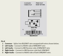
. I went to radio shack and found the jack that I needed Part# 274-246. Here are some pics of the installation.


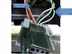
Here are the two connectors form the HU. The wires you want are in the black 12 pin connector.


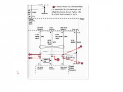
Here are the 3 wires you will be working with. The Brown/White is the left audio, the Green/White is the right audio, and the Black/White is the common. You need to cut the BRN/WHT and GRN/WHT wires but not the BLK/WHT. leave enough wire on the radio plug side to be able to splice into. I have already cut the wires in this pic.


Here is a diagram of the wire connections that you need to make


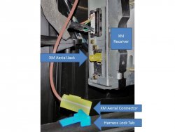
Where I mounted the jack.


My MP3 player connected and working through the system.

Just put the radio on XM1 or XM2 and when something is plugged into the jack it disconnects the XM and plays whatever is plugged in. The radio still displays the name of the XM station that it was tuned to but that does not bother me at all. I am very satisfied with this mod and thought that some others might be interested in a low cost alternative to the aftermarket adapters.
Any questions just let me know.
Happy Modding
I have a 2006 Trailblazer without XM or OnStar. Could I splice into the wires to install a aux audio connection?
 
Back
Top