• If you currently own, previously owned or want to own an Avalanche, we welcome you to become a member today. Membership is FREE, register now!

OnStar (VCIM) Tech info.

sperry

Silent Avalanche RIP
SM 2007
SM 2006
SM 2005
Full Member
Joined
Oct 22, 2003
Messages
13,160
Location
Seligman, AZ
Note: Content of this and other topics in this section, is provided for Educational/information purposes for CAFCNA members only. No content in part or entirety is to be used or referenced for commercial purposes by anyone (except GM).

OnStar DTC's:
------------------------------
DTC B2455
Circuit Description

The vehicle communication interface module (VCIM) detects that the cellular microphone is connected through the cellular microphone signal circuit and the cellular microphone low reference circuit

Conditions for Running the DTC

    * The ignition must be in the RUN or ACC position.
    * The system voltage is at least 9.5 volts and no more than 15.5 volts.
    * All the above conditions are present for greater than 10 seconds.

Conditions for Setting the DTC

    * The VCIM detects an open in the cellular microphone signal circuit or drain wire circuit.
    * The VCIM detects a short to voltage in the cellular microphone signal circuit.
    * The above conditions are present for greater than 10 seconds.

Action Taken When the DTC Sets

    * The VCIM will not receive any signal from the microphone.
    * Calls can be placed but the caller cannot be heard.
    * The OnStar? status LED turns RED.

Conditions for Clearing the DTC

    * The VCIM detects the microphone connected for 5 consecutive 100 millisecond cycles.
    * A history DTC clears after 50 malfunction free ignition cycles.
    * The VCIM receives the clear DTC command from the scan tool.

 
DTC B2470

Circuit Description

The cellular portion of the cellular and navigation antenna is connected to the vehicle communication interface module (VCIM) with a RG-174 coax cable. The VCIM polls the data from the antenna once every second.

Conditions for Running the DTC

    * The ignition must be in the RUN or ACC position.
    * The system voltage is at least 9.5 volts and no more than 15.5 volts.
    * All the above conditions are present for greater than 1 second.

Conditions for Setting the DTC

    * The VCIM does not detect the presence of the cellular antenna
    * All the above conditions are present for greater than 1 second.

Action Taken When the DTC Sets

    * The OnStar? status LED turns RED.
    * The vehicle is unable to connect to the OnStar? Call Center.

Conditions for Clearing the DTC

    * The VCIM detects the presence of the cellular and navigation antenna.
    * A history DTC clears after 50 malfunction free ignition cycles.
    * The VCIM receives the clear DTC command from the scan tool.
 
DTC B2476

Circuit Description

The OnStar? button assembly consists of three buttons, Call/Answer, OnStar? Call Center and OnStar? Emergency. Ten volts is supplied to the button assembly on the keypad supply voltage circuit. Each of the buttons, when pressed, completes the circuit across a resister allowing a specific voltage to be returned to the vehicle communication interface module (VCIM) on the keypad signal circuit. Depending upon the voltage range returned, the VCIM is able to identify which button has been pressed.

Conditions for Running the DTC

    * The ignition must be in the RUN or ACC position.
    * The system voltage is at least 9.5 volts and no more than 15.5 volts.
    * All the above conditions are present for greater than 300 ms.

Conditions for Setting the DTC

    * The keypad signal circuit voltage to the VCIM is less than 2.8 volts or more than 3.2 volts.
    * The above conditions are present for greater than 300 ms.

Action Taken When the DTC Sets

    * The VCIM will ignore all inputs from the OnStar? button assembly.
    * No calls can be placed.
    * The OnStar? status LED turns RED.

Conditions for Clearing the DTC

    * The keypad signal circuit voltage is between 2.8 volts and 3.2 volts.
    * A history DTC clears after 50 malfunction free ignition cycles.
    * The VCIM receives the clear DTC command from the scan tool.
 
DTC B2482

Circuit Description

The OnStar? button assembly consists of three buttons, Call/Answer, OnStar? Call Center and OnStar? Emergency. Ten volts is supplied to the button assembly on the keypad supply voltage circuit. Each of the buttons, when pressed, completes the circuit across a resister allowing a specific voltage to be returned to the vehicle communication interface module (VCIM) on the keypad signal circuit. Depending upon the voltage range returned, the VCIM is able to identify which button has been pressed.

    * The ignition must be in the RUN or ACC position.
    * The system voltage is at least 9.5 volts and no more than 15.5 volts.
    * All the above conditions are present for greater than 15 seconds.

Conditions for Setting the DTC

    * A button is pressed or stuck for more than 15 seconds.
    * The above conditions are present for greater than 15 seconds.

Action Taken When the DTC Sets

    * The VCIM will ignore all inputs from the OnStar? button assembly.
    * No calls can be placed.
    * The OnStar? status LED turns RED.

Conditions for Clearing the DTC

    * The button will be declared unstuck after a 50 ms normal cycle.
    * A history DTC clears after 50 malfunction free ignition cycles.
    * The VCIM receives the clear DTC command from the scan tool.
 
DTC B2483 or B2484

Circuit Description

The navigation portion of the cellular and navigation antenna is connected to the vehicle communication interface module (VCIM) with a RG-174 coax cable. The VCIM polls the data from the antenna once every second.

Conditions for Running the DTC

    * The ignition must be in the RUN or ACC position.
    * The system voltage is at least 9.5 volts and no more than 15.5 volts.
    * All the above conditions are present for greater than 1 second.

Conditions for Setting the DTC

    * The VCIM does not detect a navigation signal.
    * All the above conditions are present for greater than 1 second.

Action Taken When the DTC Sets

    * The OnStar? status LED turns RED.
    * The OnStar? Call Center cannot locate the vehicle.

Conditions for Clearing the DTC

    * The VCIM detects the presence of the cellular and navigation antenna.
    * A history DTC clears after 50 malfunction free ignition cycles.
    * The VCIM receives the clear DTC command from the scan tool.
 
DTC U1500

Circuit Description

This DTC indicates an internal fault and is set within the vehicle communication interface module (VCIM). No external circuits are involved.

Conditions for Running the DTC

The microprocessor runs the program to detect an internal fault during module power up and every 10 seconds thereafter until the module re-enters the sleep mode.

Conditions for Setting the DTC

The VCIM detects an internal communication malfunction.
Action Taken When DTC Sets

    * The OnStar? status LED turns RED.
    * The vehicle is unable to connect to the OnStar? Call Center.

Conditions for Clearing the DTC

    * A current DTC clears when the malfunction is no longer present.
    * A history DTC clears after 50 malfunction free ignition cycles.

Diagnostic Aids

    * The diagnostic procedure used for DTC U1500 in OnStar? systems with single module generations of OnStar? differ greatly from previous generations with 2 modules. While these older generations denoted a failure of the 3-wire bus between the modules by setting a U1500, single module OnStar? systems use this DTC to denote an internal module failure. The determination of whether a one or 2-module generation of OnStar? is used should be confirmed. Refer to OnStar Description and Operation .
    * This DTC may be stored as a history DTC without affecting the operation of the module. If stored only as a history DTC and not retrieved as a current DTC, do not replace the VCIM.
    * If this DTC is retrieved as both a current and history DTC, replace the VCIM.
 
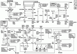
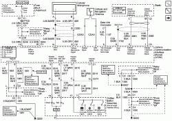
05 (V6.x) Onstar Wiring Diagram.

The image expands; how, depends on your browser.
 

Attachments

  • 1464854-05_OnStar_Wir-s.gif
    1464854-05_OnStar_Wir-s.gif
    61.5 KB · Views: 557
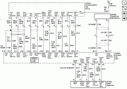
03~05 OnStar System Connections:

This image is no larger in pixel size.
 

Attachments

  • 1469071-05_OnStar_Conn.gif
    1469071-05_OnStar_Conn.gif
    32.9 KB · Views: 518
03 OnStar System Diagram - Luxury/Y91.

The image expands; how depends on your browser.
 

Attachments

  • 841751-03_Lux_OnStar_Wir-s.gif
    841751-03_Lux_OnStar_Wir-s.gif
    86.7 KB · Views: 518
03 OnStar System Diagram - Non-Lux

The image expands; how, depends on your browser.
 

Attachments

  • 841747-03_Non_Lux_OnStar_Wir-s.gif
    841747-03_Non_Lux_OnStar_Wir-s.gif
    74.4 KB · Views: 601
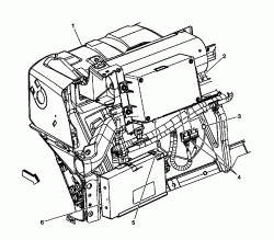
03~05 OnStar VCIM Location

(1) Instrument Panel (I/P)
(2) Vehicle Communication Interface Module (VCIM)
(3) Cellular Antenna Coax
(4) VCIM Connectors
(5) Navigation Antenna Coax
(6) Digital Radio Receiver (U2K/U2L)


The image expands; how, depends on your browser.
 

Attachments

  • 851799OnStBox-Loc.gif
    851799OnStBox-Loc.gif
    33.7 KB · Views: 813
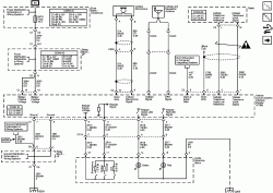
02 OnStar Wiring Diagram VCU - VIU, Mic & Buttons

The image expands; how, depends on your browser.
 

Attachments

  • 701587-02-OnStarWir_Sch.gif
    701587-02-OnStarWir_Sch.gif
    84.6 KB · Views: 519
Back
Top