spetch
Full Member
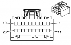
Does anyone have a diagram that shows the pin-outs for the connector going into the instrument panel cluster?
")
here you go
Pin Wire Color Function
A1 BRN/WHT MIL Control
A2 Not Used
A3 BLK/WHT Low Washer Fluid Indicator Supply Voltage
A4 DK GRN/WHT Vehicle Speed Signal
A5 WHT Engine Speed Signal
A6 GRY IPC Class 2 Serial Data
A7 Not Used
A8 DK BLU Right Turn Signal Lamps Supply Voltage
A9 Not Used
A10 DK GRN/WHT Transmission Shift Select Switch (Park) Signal
A11 RED Instrument Panel Lamps Dimming Supply Voltage
A12 BLK Ground
B1 LT BLU Left Turn Signal Lamps Supply Voltage
B2-B3 Not Used
B4 ORN DIC Mode Switch Signal
B5 DK BLU DIC Toggle Switch Signal
B6 DK GRN/WHT DIC Switch Signal
B7 YEL DIC Fuel Signal
B8 Not Used
B9 PNK Ignition 1 Voltage (w/o 8S
PNK Ignition 1 Voltage (w/ 8S
B10 Not Used
B11 ORN Battery Positive Voltage (w/o 8S
ORN Battery Positive Voltage (w/ 8S
B12 BLK/WHT Ground
Probably thru the CANbus messages. i.e. computer LAN network from ECMI have a 05 Silverado and this is the exact pin out I have how does the cluster receive oil pressure readings and coolant temp reading. What is the pin location for those 2
what lights are out? Depending on what light they are mini bulbs soldered to the board.Anyone have a schematic for the backlight of dash and climate control?