Questions

let me know before you start. ?If something is not clear let me know before you start.
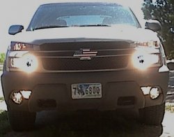
All forward lights on at once.
Mod that will turn Daytime Running Lamps (DRL) fog lights, High and Low headlights all on at the same. ?Does not require drilling or adding switches.
Prerequisites; Single wire headlamp modification if you want low beam headlights to stay on when you turn on the high beams. ?Otherwise only high beams, fog and DRL will be lit.
Basic operation. ?When the headlights come on using the automatic system the fog & DRL lamps work normally. ?When the manual head light switch is used (when was the last time you really used it

) the lights still all work normally until you switch on the high beams. ?With the manual switch on (headlamp position not parking lights) and the high beams selected the Low beams, High beams, DRL?s and Fog lights are all on. ?When you switch back to lows (with the manual switch still on) only the lows stay on, the rest go out. ?You can switch the fog lights back on (normal operation) by pushing the fog lamp button.
Used common parts from Radio shack. ?Goal was to make it all off the shelf parts and keep the cost down. ?All parts used can be swapped out if you have a suitable replacement. ?This mod adds an extra way to get input to the DRL and fog lamp control signals. ?So no high current parts are required. ?In fact the parts I used are over rated but the convenience they offered offset any small cost advantage.
Tools / parts needed (beyond what you probably already have)
Volt / Ohm meter
5 pieces of 3 to 4 feet of 22 gauge wire (Preferred colors Green, White, Black, Purple)
Soldering iron and solder (Don?t care for squeeze on connectors)
1 Ring style wire connector
3 feet of heat shrink 3/16 inch and 5/16 diameters
Several Zip ties
4 female spade connectors (will fit onto relay)
1 Relay (Radio Shack part number 275-226 cost $5.99)
4 diodes (Radio Shack part number 276-1114 cost $1.69 x 2 = $3.3
A nut and bolt to mount the relay (found and aero nut and bolt in the garage)
Two to three hours without the kids, dog, wife and beverage of choice.
Steps:
1) ? ? ?Determine a suitable location to mount the relay. ?I used the underside of the drivers side cowl bracket (the one you remove in step three). ?It has a hole already drilled in it that matches the hole size of the relay I used. ?Whatever location you chose this is were the wires from the fuse box will end at.
2) ? ? ?Disconnect the battery negative terminal ?(MUST DO THIS, or you may get a repeat of the 4th of July).
3) ? ? ?Remove the left side (drivers side) fender to cowl bracket. ?It is a curved bracket that goes across part of the fuse box in the engine compartment. ?Four bolts, two on the cowl and two on the fender hold it on. ?Note: I mounted the relay to the underside of this bracket.
4) ? ? ?Remove the cover from the fuse box in the engine compartment.
5) ? ? ?Carefully release the tabs holding the main body of the fuse box and lift it up
6) ? ? ?Tilt the main body of the fuse box so you can see the junction blocks on the bottom.
7) ? ? ?Locate the long Gray colored block (Block C1 for those with a service manual)
? ? ?Unbolt the Gray block.
9) ? ? ?Cut the small zip ties holding the wire bunches (need working room).
10) ? ? ?Locate the two white wires at E8 (the connector is done in a row column manner. ?The letters are on the short side A to F, and the numbers on the long side 1 to 12. ?There are fine markings on the sides of the connector.)
11) ? ? ?Remove the pin safety for the white wires you just found. ?The safety is a blue piece of plastic used to prevent the wires from coming out of the connector. ?It should just slide out.
12) ? ? ?Using an ice pick carefully release the locking tab holding the white wires to the gray connector. ?You should now have the two white wires connected to a single metal connector.
13) ? ? ?READ CAREFULLY, THIS IS THE ONLY STEP THAT IS NOT FOOLPROOF (any coincidence it?s step 13??..)You will need to cut the white wire that feeds to the manual light switch, but there is no easy way of knowing which one of the two wires. ?The other white wire feeds to the Body Control Module and is used for automatic headlight operation. ?There is 50 / 50 chance of getting the correct wire. ?If you get the wrong wire you will have to splice the wire back together and redo with the correct wire. ?If you do have to splice the wire back make sure you solder them back to together and cover the connection with heat shrink. ?On my AV this was how they were orientated, no guarantees all wire harnesses are the same. Standing of the drivers? side facing into the engine compartment, hold the connector for the two wires so that the copper part is also facing into the engine compartment, you should see no copper and a hole in the center on the metal connector. ?The wire to the right is the wire I cut. ?Make the cut about 1.5 to 2 inches down from the base of the metal connector.
14) ? ? ?Strip ? an inch of insulation from each end of the cut wire.
15) ? ? ?Test if you cut the correct wire. ?Reinsert the gray block back into the main housing. ?Do not insert the metal connector from the wire you just cut into the block, let it hang free. ?Do NOT reconnect the battery. ?Connect one end of your OHM meter to the wire you just cut (not the side with the metal connector and the other end to the positive battery terminal (use the battery jump post). ?You should get little or no reading , high resistance. ?Turn the manual headlight switch on to the headlamp setting. ?The meter should now show little or no resistance. ?If not, swap the meter connection on the white wire to the side with the metal terminal. ?Retest. ?If the meter now drops to zero resistance with the manual switch on and goes to high resistance with it off then you cut the wrong white wire. ?Make any necessary corrections. ?By the way I got lucky and cut the correct wire the first time. ?Alternate test method without a meter (did not try but should work, in theory). ?Insert the metal connector back into E8, make sure the cut ends of the white wires do not touch anything, may need to temp cover with tape, reinstall the gray block, reconnect the negative battery cable to the battery. ?Turn the manual switch to on. ?The headlights should not come on. ?Cover the two light sensors on the dash with a dark towel. ?Manual switch off, start the AV, put it in gear and release the parking brake. ?The headlights should come on. ?If so you have cut the correct wire. ?If the manual switch operates the lights and the automatic sensor does not then you have cut the wrong wire. ?Undo the battery cable when done testing or when removing the gray block from the main block.
16) ? ? ?Once the correct wire is identified, remove the gray block from the main block
17) ? ? ?Slide two pieces of 2 inch long heat shrink (5/16 inch) on the cut wire and move them down far enough to be out of the way.
1
? ? ?Connect, solder, two diodes to the cut wire (not the wire still connected to the metal connector). ?The white stripe on both diodes must be at the opposite end of the connection. ?That is the wire and the diodes must be connected on the black side of the diode. ?When done you should have a white wire with two diodes attached to the wire and the other ends of the diodes (the side with the white strip) going nowhere, yet. ?Kind of looks like a ?Y?.
19) ? ? ?Connect; solder the other end of the cut wire (the short piece still connected to the metal connector) to one of the diodes. ?Does not matter which one.
20) ? ? ?Solder a piece of wire to the other diode. ?I will call this the new white wire. ?This wire will need to be long enough to reach the new relay. This wire will carry a positive voltage to the relay coil when the manual headlamp switch in turned on (keep this in mind for testing if you have problems).
21) ? ? ?Slide one piece of heat shrink over the connections it should cover all the exposed connections. ?Shrink it. ?Repeat with the second piece over the first. ?This just adds extra strength. ?The diodes should be safely in the center of the heat shrink. ?Do not bend were the diodes are.
22) ? ? ?Reinsert the metal connector back into the gray block at E8.
23) ? ? ?Locate the light green and black wire at F7 on the gray block.
24) ? ? ?Remove it from the block using an ice pick to free the lock tab. ?Make sure the blue safety clip is also out.
25) ? ? ?Strip some insulation from the wire WITHOUT cutting the wire.
26) ? ? ?Wrap the black side of the diode around the exposed insulation and solder the diode to the wire.
27) ? ? ?Solder a new green wire to the other side of the diode (the side with the white stripe).
2
? ? ?Slide heat shrink over the metal connector so it covers the diode and all exposed solder joints. ?Shrink it and repeat with a second piece of heat shrink.
29) ? ? ?Reinsert the metal connector back into the gray block at F7.
30) ? ? ?Locate the Dark green and white wire at B3 on the gray block.
31) ? ? ?Remove it from the block using an ice pick to free the lock tab. ?Make sure the blue safety clip is also out.
32) ? ? ?Strip some insulation from the wire WITHOUT cutting the wire.
33) ? ? ?Wrap the black side of the diode around the exposed insulation and solder the diode to the wire.
34) ? ? ?Solder a new green wire to the other side of the diode (the side with the white stripe).
35) ? ? ?Slide heat shrink over the metal connector so it covers the diode and all exposed solder joints. ?Shrink it and repeat with a second piece of heat shrink.
36) ? ? ?Reinsert the metal connector back into the gray block at B3.
37) ? ? ?Connect the two new green wires together. In a ?T? fashion. ?That is, each of the two new green wires should be about 5 inches long and connected to each other with another new green wire connected between the first two new green wires. ?The third new green wire needs to be long enough to reach the relay. ?The two short pieces will remain hidden inside the main fuse block. ?What you have done is connect the Fog and the DRL control lines together. ?The diodes prevent the DRL turning on the Fog lights and the Fog lights from turning on the DRL in normal operation.
3
? ? ?Cover the connection were the three green wires meet with heat shrink. (testing note: when this wire is shorted to ground it will turn the DRL and fog lam relays on).
39) ? ? ?Locate the two Purple wires at C3 on the gray block.
40) ? ? ?Remove it from the block using an ice pick to free the lock tab. ?Make sure the blue safety clip is also out.
41) ? ? ?Strip some insulation from the wire WITHOUT cutting the wire.
42) ? ? ?Solder a piece of new purple wire around the exposed insulation.
43) ? ? ?Slide a piece of heat shrink over the connection and shrink it. (testing note: this is the negative side of the highbeam switch, when the switch is in the high beam position this wire will show no resistance to ground, when the switch is in the low position you will get no meter reading, high resistance, when measured to ground).
44) ? ? ?Reinsert the metal connector back into the gray block at C3
45) ? ? ?Put the blue safety pins back in.
46) ? ? ?Reinsert the gray connector into the main
block (check the orientation should only go one way.) ?Bolt the connector back to the main block
47) ? ? ?Zip tie up any necessary wires.
4
? ? ?Set the main block back into its bracket. ?Make sure the unconnected ends of the new wires come out of the block. ?I used the opening to the right (closest to the windshield). ?You should have three new wires coming out of the block. Snap into place.
49) ? ? ?Put the cover back on the block.
50) ? ? ?Solder one end of the new Black wire to the ring connector.
51) ? ? ?Attach the ring connector to ground. ?I used the ground bolt below the light inside the hood. ?There is a braded metal ground strap connected to it. ?Be careful not to over torque this bolt, it will snap off. ?
52) ? ? ?Run the new black wire to where the relay will be located.
53) ? ? ?Reinstall the metal fender to cowl bracket
54) ? ? ?Solder the spade connectors to each end of the new wires.
55) ? ? ?Connect the wires to the relay. ?The white wire goes to one side of the relay coil and the purple goes to the other side of the relay coil. ?The green goes to one side of the relay contacts and the black goes to the other.
56) ? ? ?Mount the relay so no connectors touch. ?Under the curved fender to cowl bracket works great.
57) ? ? ?Reconnect the battery.
5
? ? ?Done, Enjoy.
To undo this mod simply disconnect the white wire from the relay and cover the wire up so it does not short out on anything. ?The rest of the components you can leave in place. ?They will not have any effect on normal operation


 , especially after they get wet from salt water. Abalone & halibut dive trips